Saturday, August 9, 2008

Chemical Engineering Digital Issue for August 2008

Display problem ? Click HERE


Chemical Engineering Digital Issue for August 2008 has released !
Chemical Engineering magazine has just released August 2008 issue. If you are the subscriber of Chemical Engineering, you shall received similar notification. The new digital version is claimed to be fully compatible with most web browsers.

Few interesting articles in Chemical Engineering August 2008 :
  • Making Energy Efficiency Pay
  • Novel and Conventional Approaches to Sterilization
  • Predicting Physical Properties of Hydrocarbon Compounds
  • A Lessons-Learned Knowledge Management System for Engineers
  • Prevent Caking And Unintended Agglomeration
If you yet to be subscriber of Chemical Engineering, requested your FREE subscription via this link (click HERE).

Related Post

Wednesday, August 6, 2008

Relate Normal to Actual Volumtric Flow

Display problem ? Click HERE

Recommended :
Subscribe FREE - Chemical Processing

There was a question raised in CR4 forum related to conversion from Nm3/h to m3/h and the equation can be known by many of you. Nevertheless, the derivation and relation in between ideal gas and real gas and the derived equation could be useful and handy for some of you.

First for most important thing is the definition of Normal and actual condition. Normal condition in this case is define as 1 ATM @ 0 degC whilst actual is at P @ T.

From Universal gas law for ideal gas,

PV = (m/MW) RT [Eq.1]

where
P = the absolute pressure of the gas, in Pa
m = mass, in kg
MW = molecular weight, in kg-mole
V = the volume of the gas, in m3
T = the absolute temperature of the gas, in K
R = the universal gas law constant of 8.3145 m3·Pa/(mol·K)

To relate it to real gas condition, compressibility factor (z) is added.

PV = z (m/MW) RT. [Eq.2]

At condition 1 ==> P1 x V1 = z1 (m1 / MW1) R x T1 [Eq.3]
At condition 2 ==> P2 x V2 = z2 (m2 / MW2) R x T12 [Eq.4]

Same gas composition and flow or quantity
==> MW1=MW2, m1=m2,

[Eq.4] / [Eq.3]
==> (P2/P1) x (V2/V1) = (z2/z1) x (T2/T1)
==> V2 = (z2/z1) x (T2/T1) x (P1/P2) x V1

Using Volumetric rate (Q),
==> Q2 = (z2/z1) x (T2/T1) x (P1/P2) x Q1

If condition 2 is actual (act) and condition 1 is normal(N) (i.e. 1.01325 bar abs @ 0 degC)

At Normal condition Z1=Zn~1, P1 = 1.01325 bar abs

Qact = zact x QN x (Tact / 273.15) x (1.01325 / Pact)

where
Qact in m3/h
Pact in bar abs
QN in Nm3/h
Tact in K

Above equation with inclusion of compressibility factor to relate ideal to real gas condition,The zact factor could be range from 0.5 to 1.2 subject to composition, pressure and temperature. At low pressure, z could be closed to 1.

Tuesday, August 5, 2008

PSV Chaterring is Destructive...The ways to Prevent...

Display problem ? Click HERE

Recommended :
- Subscribe FREE - Chemical Engineering
- Tips on Succession in FREE Subscription

Pressure Relief Valve Chatter is rapid reciprocating motion of the disc where the disc contacts with the seat in cyclic motion. Flutter is similar to chatter except the disc does not contact with the seat during cyclic motion.


Why Chatter is destructive ?
Chatter is destructive where it repetitive and rapid reciprocating disc knock on the valve seat may cause

i) damage to the disc & valve seat lead to leakage and passing
ii) damage to bellow lead to gas leak via bonnet vent
iii) damage to the PRV itself and interconnecting piping through vibration
iv) severe noise level

How does PSV Sound and Looks Like ?
The following video clip shows a PSV chattering due to high back pressure.


(Click to view Video Clip in Browser)

What Factor Cause PSV Chatter ?
There are at least five factors causing PSV chatter :

i) High built-up back pressure i.e Conventional PSV built-up back pressure exceeded 10% of its set pressure. Read more in "Several Impact of Backpressure on Conventional PRV"
ii) Excessive inlet pressure drop i.e pressure drop exceeded 3% of its set pressure
iii) Large PSV handling small relief flow
iv) Accelerated liquids in long inlet line knocking at pop acting PSV
v) Multiple PSVs with same pressure setting

Recommended :
- Subscribe FREE - Power Engineering (USA, Canada & Mexico)
- Subcribe FREE - Power Engineering (International)

How to Avoid PSV Chatter ?
A few ways to avoid PSV chatter are tabulated :

i) Install correct type of PSV. If conventional spring loaded PSV is installed, ensure the built-up back pressure shall always lower than 10% it set pressure. Otherwise, use balanced type.
ii) Ensure inlet line loss is below 3% of it set pressure as recommended by API. If exceeded this limit, may consider reset PSV blowdown and install pilot operated PSV with pilot sensing on protected vessel.
iii) Do not install over-designed (orifice area) PSV to handle small relieve load
iv) Install correct type PSV for liquid handling valve i.e. modulating type PSV
v) Staggered set pressure to allow chasing between PSVs.

Related Posts

Monday, August 4, 2008

Quick Check Pump Performance Using Motor Data and Field Measure Current

Display problem ? Click HERE

Recommended :
- Subscribe FREE - World Pumpv (USA & Europe only)
-
Tips on Succession in FREE Subscription

There is a centrifugal pump working on the field and a flow meter is continuously measuring the flow rate delivered by the centrifugal pump. You noticed that flow meter indicating flow rate same as normal recorded flow rate, however, the downstream system indicating that there is reduction in flow. Flow meter Calibration is one of the normal way to confirm if the flow meter is working correctly. Prior to this, you may consider the following approach to quickly check if the pump delivering good flow and cross check with the flow meter.

This approach basically use the field tested pump curve as follow.


Field tested pump curve

Pump power consumed by pump shaft,

Es = (dH x Q x SG) / (3960 x Pump Eff. x Kv) [Eq. 1]

where,
Es = Pump shaft power (HP) consumed
dH = Pump head (ft)
SG = fluid specific gravity
Pump Eff. = Pump efficiency
Kv = Viscosity Correction Factor

Power deliver by a motor to pump shaft,

Em = (1.732 x V x I x Motor Eff. x P.F.) / (746) [Eq. 2]

where,
Em = Power deliver by motor to pump shaft
V = Voltage (v)
I = Current (amp)
Motor eff. = Motor efficiency
P.F. = Motor Power Factor

Recommended :
- Subscribe FREE - Power Engineering (USA, Canada & Mexico)
- Subcribe FREE - Power Engineering (International)

Case study
A centrifugal pump transferring water from tank to a drum. A pressure transmitter located on the pump discharge. This estimated pump head based on differential pressure is 2000 ft. Fluid SG is 0.9932. From field, Voltage and current for the centrifugal pump are 460 volts and 323.1 amp. The flow meter is indicating flow rate of 385 gpm. Check if the flow meter is correctly measuring the flow rate.

From motor catalog, you may obtain motor efficiency (motor Eff.) and power factor (P.F.). For example, a motor with Motor Eff = 95% and P.F.=90%. The motor efficiency and P.F. may varies a bit (2%-5%). But they can be assumed same.

Power consumed / delivered,
From [Eq. 2],
==> Em = (1.732 x V x I x Motor Eff. x P.F.) / (746)
==>
Em = (1.732 x 460 x 323.1 x 0.95 x 0.9) / (746)
==>
Em = 295 HP

From above pump curve,
With Em = 295 HP
==> Flow, Q = 400 gpm, Pump Eff. 68% and Pump Head = 2000 ft.

Q = 400 gpm > 385 gpm as measured by flow meter. This indicates that the flow meter may not perform correctly.

Cross check with [Eq. 1],
As fluid is water,
==> Kv = 1.

For other type of fluid, may check out the viscosity correction factor using curve (by HI) presented in "Quick Check if Pump Performance Curve (Water) is Good for High Viscosity Fluid".

From [Eq. 1],
==> Es = (dH x Q x SG) / (3960 x Pump Eff. x Kv)
==> Q= Es x (3960 x Pump Eff. x Kv) / (dH x SG)
==> Q= 295 x (3960 x 0.68 x 1) / (2000 x 0.9932)
==> Q = 400 gpm


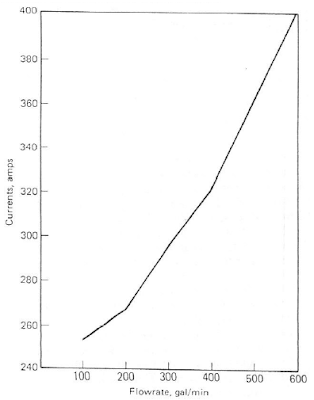
It is useful to generate a Current versus Flow curve as follow :


Current versus Flow curve

With this curve, operator may use it quickly check against the flow meter.

Sunday, August 3, 2008

Chemical & Process Technology is DOWN ?!

Display problem ? Click HERE

You may wonder why you can not viewed Chemical & Process Technology, Heat & Exchanger Technology and GenTech blogs yesterday if you are using Internet Explorer 7 (IE7). One of the main identified (but yet to confirm) "issue" is the the present of Sitemeter stats in these blogs. The Sitemeter stats has been temporary removed to resolve the crashing issue. Now the situation "recovered". If you STILL experience same problem now, appreciate you can drop me a note (click HERE).

I use FIREFOX for common browsing, there is NO PROBLEM with FIREFOX browser.

FIREFOX is a safe web browser has slowly gaining attention by many web users and stealing Internet Explorer users. Personally, i have shifted from Internet Exploer to Firefox many months ago, the experience of Firefox is so impressive, pleasing and enjoyable. Its STABIL operation and SAFE & FAST browsing really impressed me. If you haven’t got Firefox, you should really think about getting it now. Following button will direct you to install FREE Firefox in to your PC. Read more extra features in "FREE Stabil, Safe & Fast Web Browser other than IE".

If you are interested in FIREFOX (it is FREE), you may install by clicking below link (or in FREE stuff conner)


Related Post

Saturday, August 2, 2008

Relate PSV Relieving Flow to Stamped Capacity

Display problem ? Click HERE

Recommended :
- Subscribe FREE - Processing Magazine
- Tips on Succession in FREE Subscription

A pressure relief valve (PSV) is provided to protected a pressure containment system i.e. vessel and the vessel is designed for ASME Section VIII. There are several credible non-fire relieving scenario and fire scenario. The relieving flow for each scenarios and required relieving "orifice" area and size have been calculated. (sizing may refer to on API RP 520 PI - Ed 7 - Jan 2000 RP - Sizing, Selection & Installation of Pressure-Relieving Devices in Refinery). PSV datasheet for most severe condition has been submitted to PSV vendor. Vendor proposed a PSV "orifice" size with stamped capacity with steam. How do you check and confirm if this PSV is sufficient ?

Background
The capacity of a safety or relief valve in terms of a gas or vapor other than the medium for which the valve was officially rated shall be determined by application of the following formulas :

For air :

Wa = CKAP sqrt(M/T) Eq. [1a]

with
C = 356
M = 28.97
T = 520 R when Wa is the rated capacity

For steam :

Ws = 51.5KAP Eq. [1b]

For any gas/vapor :

W = CKAP sqrt(M/T) Eq. [2]

where :
Wa = rated capacity, converted to lb / hr of air at 60°F, inlet temperature
Ws = rated capacity, converted to lb/hr steam
W = flow of any gas or vapor, lb / hr
C = constant for gas or vapor which is function of the ratio of specific heats, k = Cp / Cv
K - coefficient of discharge
A = actual discharge area of the safety valve, sq in.
P = (set pressure × 1.10) plus atmospheric pressure, psia
M =molecular weight
T = absolute temperature at inlet (°F + 460)

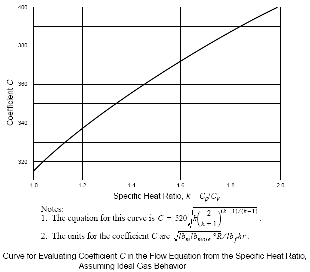
Constant C can be evaluated with the following chart and equation.


(Click image to view larger image)
Recommended :
- Subscribe FREE - Processing Magazine

Case


A PSV is required to relieve 1000 lb/h of Ammonia (M = 17.03) with a set pressure of Ps, inlet temperature of 150 degF (at 110% of Ps) and k=1.33. Vendor A has proposed a PSV A with stamped capacity of 950 lb/h at pressure same as 110% of Ps. Vendor B has proposed a PSV B with stamped capacity of 1200 lb/h at pressure same as 160% of Ps. Please check if the proposed PSV A and/or PSV B is sufficient.

W = 1000 lb/h
M = 17.03
T = 150 degF = 150+460 R = 610 R
k = 1.33
C = 520 sqrt [k(2/(k+1)^(k+1)/(k-1)] = 349.8 (say ~350)

From Eq. [2],
W = CKAP sqrt(M/T)
==> 1000 = 350 KAP sqrt(17.03 / 610)
==> KA = 1000 / [350 sqrt(17.03 / 610)]
==> KA = 17.1 / 1.1Ps

For PSV A
From Eq. [1b],
Ws = 51.5KAP
==> Ws = 51.5 (17.1 / 1.1 Ps) (1.1 Ps)
==> Ws = 881.2 lb/h

The required equivalent steam flow at pressure of 1.1Ps is 881.2 lb/h.
Proposed PSV A with stamped capacity of 950 lb/h steam is more than 881.2 lb/h steam. Thus, the proposed PSV A is sufficient.

For PSV B
From Eq. [1b],
Ws = 51.5KAP
==> Ws = 51.5 (17.1 / 1.1 Ps) (1.6 Ps)
==> Ws = 1281 lb/h

The required equivalent steam flow at pressure of 1.6Ps is 1281 lb/h.
Proposed PSV with stamped capacity of 1200lb/h steam is less than 1281 lb/h steam. Thus, the proposed PSV B is insufficient.

One shall take note that the KA for steam and gas/vapor are usually (but not always) same. It can be considered same.

Concluding remark
Above briefly discuss the relationship between a PSV relieving and PSV stamped capacity. A stamped capacity is a useful equivalent parameter to relates it to any relieving fluid & load.

Related Post