Showing posts with label Flowmeter. Show all posts

Monday, August 4, 2008

Quick Check Pump Performance Using Motor Data and Field Measure Current

Display problem ? Click HERE

Recommended :
- Subscribe FREE - World Pumpv (USA & Europe only)
-
Tips on Succession in FREE Subscription

There is a centrifugal pump working on the field and a flow meter is continuously measuring the flow rate delivered by the centrifugal pump. You noticed that flow meter indicating flow rate same as normal recorded flow rate, however, the downstream system indicating that there is reduction in flow. Flow meter Calibration is one of the normal way to confirm if the flow meter is working correctly. Prior to this, you may consider the following approach to quickly check if the pump delivering good flow and cross check with the flow meter.

This approach basically use the field tested pump curve as follow.


Field tested pump curve

Pump power consumed by pump shaft,

Es = (dH x Q x SG) / (3960 x Pump Eff. x Kv) [Eq. 1]

where,
Es = Pump shaft power (HP) consumed
dH = Pump head (ft)
SG = fluid specific gravity
Pump Eff. = Pump efficiency
Kv = Viscosity Correction Factor

Power deliver by a motor to pump shaft,

Em = (1.732 x V x I x Motor Eff. x P.F.) / (746) [Eq. 2]

where,
Em = Power deliver by motor to pump shaft
V = Voltage (v)
I = Current (amp)
Motor eff. = Motor efficiency
P.F. = Motor Power Factor

Recommended :
- Subscribe FREE - Power Engineering (USA, Canada & Mexico)
- Subcribe FREE - Power Engineering (International)

Case study
A centrifugal pump transferring water from tank to a drum. A pressure transmitter located on the pump discharge. This estimated pump head based on differential pressure is 2000 ft. Fluid SG is 0.9932. From field, Voltage and current for the centrifugal pump are 460 volts and 323.1 amp. The flow meter is indicating flow rate of 385 gpm. Check if the flow meter is correctly measuring the flow rate.

From motor catalog, you may obtain motor efficiency (motor Eff.) and power factor (P.F.). For example, a motor with Motor Eff = 95% and P.F.=90%. The motor efficiency and P.F. may varies a bit (2%-5%). But they can be assumed same.

Power consumed / delivered,
From [Eq. 2],
==> Em = (1.732 x V x I x Motor Eff. x P.F.) / (746)
==>
Em = (1.732 x 460 x 323.1 x 0.95 x 0.9) / (746)
==>
Em = 295 HP

From above pump curve,
With Em = 295 HP
==> Flow, Q = 400 gpm, Pump Eff. 68% and Pump Head = 2000 ft.

Q = 400 gpm > 385 gpm as measured by flow meter. This indicates that the flow meter may not perform correctly.

Cross check with [Eq. 1],
As fluid is water,
==> Kv = 1.

For other type of fluid, may check out the viscosity correction factor using curve (by HI) presented in "Quick Check if Pump Performance Curve (Water) is Good for High Viscosity Fluid".

From [Eq. 1],
==> Es = (dH x Q x SG) / (3960 x Pump Eff. x Kv)
==> Q= Es x (3960 x Pump Eff. x Kv) / (dH x SG)
==> Q= 295 x (3960 x 0.68 x 1) / (2000 x 0.9932)
==> Q = 400 gpm


It is useful to generate a Current versus Flow curve as follow :


Current versus Flow curve

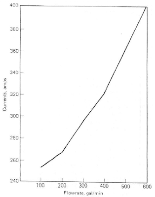
With this curve, operator may use it quickly check against the flow meter.

Friday, July 25, 2008

Special Flowmeter & Piping Release...

Display problem ? Click HERE

CLICK HERE to Subscibe FREE...

Chemical Engineering (CE) released a special issue for Flowmeter & Piping recently. There are available FREE for subscribers. If you are not a CE subscriber yet, you may subscribes FREE issue of CE*** by clicking this link.


***The CE subscription is hot and may temporary unavailable. If it is unavailable, you are encouraged to revisit the link one week after. FREE CE subscription only for qualified professional.

Managing Measurement Costs in Automated Water Treatment Systems Using Smart Sensing and Blind Transmitter Technology
By Dave Vollaire, GF Piping Systems
Installed cost per measurement is an important factor for industrial water and wastewater treatment professionals focused on system design. Modern treatment systems are highly automated and a significant portion of equipment and installation cost belongs to measurement and instrumentation components. When installation costs are removed from the equation, it becomes clear that measurement and instrumentation components alone can account for up to 50 percent of the total equipment cost. Newer technologies such as smart sensing, multi-channel, multi-parameter instrumentation, as well as blind transmitter technology, can significantly reduce the cost per measurement over the traditional single point controller schemes in automated water treatment systems....
For CE subscriber only...Click here to read
(Not CE subscriber ? Try subscribes for FREE CE... Click HERE***)

GF Piping Systems New Metal Magmeter Configuration Expands Application Range and Versatility

By GF Piping Systems
TUSTIN, Calif. – June 26, 2008 – GF Piping Systems has added to its proven Signet 2552 Metal Magmeter family with the new Model 2552-3. The Signet Metal...
For CE
subscriber only...Click here to read
(Not CE subscriber ? Try subscribes for FREE CE... Click HERE***)

GF Piping Systems Introduces Next Generation DryLoc® pH and ORP Sensors Offering Enhanced Chemical Compatibility and Versatile Mounting Options
By GF Piping Systems
TUSTIN, Calif. – July 8, 2008 – GF Piping Systems has introduced the next generation of Signet DryLoc pH/ORP Sensors, Models 2724 − 2726. These sensors feature...
For CE subscriber only...Click here to read
(Not CE subscriber ? Try subscribes for FREE CE... Click HERE***)

GF Piping Systems Introduces USB Interface for Signet Sensors, Offering Diagnostics, Parameter Configuration and Data Monitoring Capabilities
By GF Piping Systems
TUSTIN, Calif. – Nov. 8, 2007 – GF Piping Systems has introduced the Signet 3-0250, a new interface device that allows USB connection of blind Signet Sensors to...
For CE subscriber only...Click here to read
(Not CE subscriber ? Try subscribes for FREE CE... Click HERE***)

FAYF - FLOWMETER SELECTION
by Rebekkah Marshall
Briefly discusses general selection criteria, flowmeter accuracy and turndown...
Click here...

Recommended :
Subscribe FREE - Processing Magazine

Following are 6 articles in series related to Piping for Process Plants. by W. M. Huitt, W. M. Huitt Co.

Piping for Process Plants Part 1: The Basics
Pipe, fittings and related equipment are fundamental to the operation of chemical process plants. The series of articles beginning with this one spells out the details. This is the first in a series of articles that will cover a wide range of piping topics. The topics will cross process-industry lines, pertaining to, for example, the chemical, petroleum-refining, pulp-and-paper and pharmaceutical and other industries.The main intent of these articles to address questions and misunderstandings as they relate to use of piping on a general basis.

Typical of the topics that will be covered in this series are the following:
* With respect to ASME flange ratings — Is the correct terminology 150- and 300-pound flange, or is it Class 150 and Class 300 flange? And do the 150 and 300 actually mean anything, or are they simply identifiers? Similarly, with respect to forged fittings, is the terminology 2,000-pound and 3,000-pound, or is it Class 2000 and Class 3000?
For CE subscriber only...Click here to download
(Not CE subscriber ? Try subscribes for FREE CE... Click HERE***)

Piping Design, Part 2 - Flanges
The engineer or designer must choose among several flange options. Additional decisions involve facing and surface finishes, and the appropriate gaskets, bolts and nuts. Pipe flanges are used to mechanically connect pipe sections to other pipe sections, inline components, and equipment. Flanges also allow pipe to be assembled and disassembled without cutting or welding, which eliminates the need for those two operations when dismantling is required. In providing a breakable joint, however, flanges unfortunately provide a potential leak path for the process fluid contained in the pipe. Because of this, the usage of flanges needs to be minimized where possible, as with all other joints.
For CE subscriber only...Click here to download
(Not CE subscriber ? Try subscribes for FREE CE... Click HERE***)

Piping Design, Part 3 - Design Elements
Design requires a systematic methodology, planning, technical ability, interdisciplinary coordination, foresight and, above all, experience. Piping design is the job of configuring the physical aspects of pipe and components in an effort to conform with piping and instrumentation diagrams (P&IDs), fluid-service requirements, associated material specifications, equipment-data sheets, and current good manufacturing practices (GMP) while meeting owner expectations. All of this must be accomplished within a pre-determined, three-dimensional assigned space, while coordinating the activity with that of the architecture, structural steel, HVAC (heating, ventilation air conditioning), electrical, video, data-and-security conduit and trays, and operational requirements.
For CE subscriber only...Click here to download
(Not CE subscriber ? Try subscribes for FREE CE... Click HERE***)

Piping for Process Plants, Part 4: Codes and Fabrication
Besides flanges, there are also several different types of joints and welding processes to choose from. Additional decisions involve piping codes. This fourth in a series of articles* on piping for process plants examines two topics that may, at first, seem to fall outside the scope of chemical engineering — piping codes and the pipe fabrication. Obviously chemical engineers will not be welding pipes together, but understanding the benefits and limitations of different types of welding processes, for example, can help the engineer when designing the system that needs to be welded.
For CE subscriber only...Click here to download
(Not CE subscriber ? Try subscribes for FREE CE... Click HERE***)

Piping Design Part 5: Installation and Cleaning
These practical guidelines for deciding which installation procedure to follow, and for cleaning a new pipeline system can prevent problems from happening during startup. This fifth in a series of articles [1 – 4] on piping design discusses the practical issues of installation and cleaning. The installation of pipe follows its fabrication and is very frequently a part of it. The installation of pipe can be accomplished in the following four primary ways, or combinations thereof:
For CE subscriber only...Click here to download
(Not CE subscriber ? Try subscribes for FREE CE... Click HERE***)

Piping for Process Plants Part 6: Testing & Verification
Proper documentation, determination of the fluid service category and operating conditions are among the factors necessary to perform the correct leak test on a piping system. This sixth and final part of a series of articles [ 1 – 5] on piping for process plants discusses practical issues of leak testing and verification of piping systems. Leak testing and pressure testing are often used synonymously. However, pressure testing is a misnomer when referring to leak testing of piping systems. By definition, a pressure test is the procedure performed on a relief valve to test its set-point pressure. The intent, when pressure testing a relief valve, is not to check for leaks, but to test the pressure set point of the valve by gradually adding pressure to the relief valve until it lifts the valve off of the seat.
For CE subscriber only...Click here to download
(Not CE subscriber ?
Try subscribes for FREE CE... Click HERE***)

Wednesday, July 23, 2008

Flow Element (FE) Upstream or Downstream of Control Valve (CV) ?

Display problem ? Click HERE

Recommended :
Subscribe FREE - Processing Magazine

A question raised by a young engineer.

Should a Flow element (FE) be located upstream or downstream of a control valve (CV) ?


There is no fix rules governing the location of this flow element. It is very much subject to few factors i.e. fluid condition of the measured fluid, properties fluctuation, etc.

a) Fluid Characteristic
A flow element is general prefer single vapor or liquid phase as compare to two phases gas-liquid (2Ph-GL) flow. First to check is the fluid characteristic downstream of control valve. For example, liquid control valve (LCV) maintaining level of a separator. The fluid feeding the LCV is probably a liquid at bubble point. Due to static head it potentially maintain as liquid from separator outlet nozzle upto LCV. However, there is pressure drop across the LCV and 2Ph-GL flow is likely to occur downstream of LCV. Under this condition, it is always prefer to locate flow element upstream of LCV.

Let take another example for vapor flow line. A pressure control valve (PCV) maintaining a constant saturated gas flow to downstream system i.e. fuel gas system from a separator. In the event there is large pressure drop across the PCV, Joule-Thompson (JT) effect results significant liquid formation downstream of PCV. Similarly, it is always prefer to locate flow element upstream of PCV.

b) Pressure & Temperature Fluctuation
Large pressure and temperature fluctuation would probably leads to properties (i.e density) changes. In general, a vapor system would experience severe changes as compare to liquid system. Thus, large pressure and temperature fluctuation may results a large deviation in properties and lead to difficulties in select a good flow element for the service. It is always prefer to locate flow element in the stream with "less" properties change .

For example, a slug catcher is having a pressure control valve (PCV) feeding gas to booster compression system. The booster compression is targeted to maintain a constant pressure of

Recommended :
Subscribe FREE - Chemical Processing

the suction scrubber. As slugcatcher pressure (upstream of PCV) may fluctuate due to slugging and pigging operation whilst the pressure (downstream of PCV) at compressor suction scrubber is rather constant, it is always prefer to locate flow element downstream of PCV. It shall be noted that there is potential liquid formation downstream of PCV which prefer to locate PCV upstream of PCV. Both rule-of-thumbs are contradicting between each and other, a process engineer shall weight both impacts to locate it at right location.

c) Pressure Rating
High pressure rating of flow element will be costly. Thus, it is always prefer to locate the flow element at the system with lower pressure rating, downstream of control valve.

d) Vibration
Pressure drop across control valve would partially convert its energy to noise and vibration. The vibration (higher intensity) would travel along fluid flow direction. Some flow element (i.e. Coriolis,Vortex) is sensitive to vibration. Vibration sensitive flow element is always advisable to locate upstream of control valve.

A process engineer may consider above factors to locate the flow element. Apart, process engineer is always advisable to verify this subject with instrument engineer and vendor for proper location and correct flow meter type.


Related Post

Tuesday, August 7, 2007

Use Ultra-Sonic Flowmeter in FLARE Gas Header for emission monitoring


Increasing greenhouse effect and global warming has resulted environment changed dramatically. Signing of Kyoto protocol is part of the cumulative effort to minimize global warming. Rules and regulations becoming stricter and demands for continuous flare gas measurement and recording has become one of the mandatory requirements.

Within the United States, the Environment Protection Agency (EPA, www.epa.gov) has enforced emission levels of NOx (Nitrous Oxides) and highly reactive volatile organic compounds (HRVOC) through individual states with allocations and fines. In Texas, California, and New Jersey the ozone depletion has led to stricter total emissions and monitoring of HRVOCs.. In Texas, the Texas Commission of Environmental Quality (TCEQ, www.tceq.state.tx.us) Chapter 115 Regulation has set the levels for each flare stack. The new regulations require a flare gas flowmeter to be specified to have +/- 5 percent inaccuracy at 30, 60, and 90 percent of range under its installed condition

Calculating flare gas has gone into history. One of the biggest challenges of measuring flare gas is large TURNDOWN. Flare gas flow can ranged from low fuel gas purge during normal operation to large flow during emergency relief and/or total plant blowdown.

Common flowmeter type such as differential-pressure, vortex-shedding, and insertion thermal mass meters, etc are unable to meet such low turndown requirement. Ultra-sonic flowmeter is generally used in flare gas measurement & recording. See some features and benefits of an Ultra-Sonic Flowmeter
HERE and HERE

Apart from large turndown capability (from 0.03 m/s to 85 m/s), ULTRA-SONIC flowmeter also has the following advantages in flare gas application :

- Extremely low pressure drop (virtual zero pressure drop)
- No internal, insertion and moving parts which potential create partial blockage of flare line
- Tolerate some condensed liquid
- Can take higher operating temperature (upto 260 degC)
- No affected by gas composition
- No maintenance


Thus, stringent authority requirements on flare gas measurement, ULTRA-SONIC flowmeter would be one of the best offers.

Further reading


Continue receive FREE stuff & Update.......Subscribe by Email OR RSS
Any comments / advices ?..........Drop it in comment field (below) or sent a private email to me...

Monday, July 23, 2007

CE - Evaluation and Advances in Flowmeters


CHEMICAL ENGINEERING magezine also shared the following articles within the community...If you are still fresh in Chemical and Process Industrial, I would recommend you read the first article by Jenniffer. It is simple and practical...Process / Plant expert like some of you...please proceed to second article. There are more consolidatred and philosophical / conceptual kind of approaches...
Jennifer Keith
Flow Technology, Inc
This article provides an overview of flowmeter selection criteria and practical advice for evaluating common meter designs and for pairing the right instrument technology with various flow-measurement applications is offered. Intangible factors shall also be considered which include familiarity of plant personnel, their experience with calibration and maintenance, spare parts availability, and mean time between failures at the particular installation site.
Gernot Engstler
Endress + Hauser
High demand from chemical process industry (CPI) has pushed the manufacturer to provide high performance instrumentaion and flowmetering solutions include tools for the entire life cycle of a flowmeter.
From engineering, commissioning and start up to operations and maintenance, advanced diagnostics and onsite device-verification features help to maximize plant availability, instrument reliability and cost savings. Flowmeter instrumentation can even provide process status and analysis information that can be used to increase product quality and process efficiency. In addition to requiring high performance, users increasingly look for sensors that are easy to install, commission, use and maintain. Flowmeters that are tailored to the specific requirements of an industry or application can reduce the complexity and costs of operation. In this article, we look at some of the advanced functions of flowmeters.
Further Reading


Continue receive FREE stuff & Update.......Subscribe by Email OR RSS
Any comments / advices ?..........Drop it in comment field (below) or sent a private email to me...

Sunday, July 22, 2007

FAYF - Flowmeter selection in brief...


CHEMICAL ENGINEERING magazine shared the following useful information....

<<

FLOWMETER SELECTION >>, by Rebekkah Marshall

Briefly discusses general selection criteria, flowmeter accuracy and turndown...


Continue receive FREE stuff & Update.......Subscribe by Email OR RSS
Any comments / advices ?..........Drop it in comment field (below) or sent a private email to me...