Showing posts with label Hydraulic. Show all posts

Monday, June 7, 2010

Quick Estimation of Frictional Loss in Water Network - Spreadsheet Available

Recent post "Quick Estimation of Frictional Loss in Water Network" has presented frictional loss estimation using Hazen-William equation. Ankur has recently programed it in Excel spreadsheet. You may download with by clicking this link. Any comments, please drop a notes...


Download

Thanks to Ankur


Sunday, June 6, 2010

Quick Estimation of Frictional Loss in Water Network

Firewater, service, portable and drinking water network is common network present in most Oil & gas, Refinery and Industry plant. Water balancing in this network is important and critical in maintaining a constant supply to all users. Correct frictional loss estimation within network is the key activity in providing a well balance of water supply. Hazen-William formula is one the method widely accepted and used in industry in estimating frictional loss.

Hazen-William frictional loss is a function of fluid velocity, hydraulic radius and a constant subject to fluid condition and type of pipe. Equation as follow :


C Change with Pipe Material
Hazen-William friction loss coefficient (C) subject to condition and type of pipe. It possibly range from 60 to 150. The following summary listed the Hazen-William friction loss coefficient (C) for different type of material 

(source : Handbook of Chemical Engineering Calculation)


Another set of Hazen-William friction loss coefficient also listed in NFPA 15-2007.
(source : NFPA 15-2007)

From above figures, the C factor is almost decrease with surface roughness.

C Decrease With Service Life
One shall take note that Hazen-William friction loss coefficient will decrease with service life. From King & Crocker "Piping Handbook", C = 120 when the pipe is new and decrease to C=90 after 20 years. From "Handbook of Chemical Engineering Calculation", C factor for a new Cast-iron pipe (30 inches) is 130, decrease to 120 after 5 years, decrease to 115 after 10 years, decrease to 100 after 20 years, decrease to 90 after 30 years, decrease to 80 after 40 years and decrease to 75 after 50 years.

Thursday, March 4, 2010

Control Valve Selection


Control valve has been widely used in Chemical & Process Plant for material feeding control and operating condition control, material feeding control. Today control valve technology is highly reliability and availability and long life span. It is a very mature technology. There are many handbooks and articles available online and FREE for read and download. In the past a control valve related documents listed in "Useful Documents Related to Control Valve". This time i would like to highlight a few that i think they are rather complete and you shall not miss them.


Handbook For Control Valve Sizing
Besides two most important handbooks for control valve available free in the net, Parcol is also offering Handbook for Control Valve Sizing which is brief but informative in nature.

Valve failures, replacements, repairs, downtime and lost product can be greatly minimized by selecting the right valve, the first time. Great. So how do you assure you are selecting the right valve? There are basically 3 avenues:
1. Evaluate your system criteria relative to each valve type.
2. Utilize the expertise of a consultant or the factory Technical Sales Representative.
3. Utilize one of the new Valve Selection Software Programs provided by various valve manufacturers.
Control Valves Selection
Almost any type of valve can be used for control by fitting an actuator and positioner, though care must be taken to ensure that there is no excessive backlash present and it will be recognised many will not exhibit a good characteristic for precise control. A simple comparison table is presented in this article for easy selection.

Surge is an aerodynamic flow instability which can lead to the catastrophic failure of the compressor system. One way to cope with this compressor flow instability is active control. For a laboratory-scale gas turbine installation, an active surge control system is proposed which consists of a plenum pressure sensor and a bleed / recycle valve. This work focuses on the selection of a control valve. More specifically, the required bandwidth and capacity of the valve are specified.


The control valve is the most important single element in any fluid handling system, because it regulates the flow of fluid to the process. To properly select a control valve, a general knowledge of the process and components is usually necessary. This reference section can help you select and size the control valve that most closely matches the process requirements.
 
Control Valves are the most important element of a fluid handling system and proper selection of these valves is crucial for efficient operation of the process. When sizing butterfly valves for control, it is imperative to have certain requirements of the system. Maximum flow requirement would be equivalent to the design flow and provided or converted to gallons per minute and Maximum pressure drop allowed where typically 3 to 5 pounds max. However, the pressure drop should never exceed one half (1/2) of the inlet pressure. Without these two factors, selection of a control valve would be simply a guess...

Selecting a Control Valve
Fluid velocity in a control valve is a key parameter that must be considered when sizing and selecting a control valve. High velocity can lead to erosion damage, trim wear, trim component failure, vibration and high noise levels. Therefore, it is vital to design for valve velocities within acceptable limits so that these problems are avoided. A maximum body inlet velocity of...

Compressor Anti-Surge Control Valves
Surge Control Valves must be capable to operate the compressor below the surge control line. The surge control line is always depicted to the right of the surge limit line in the compressor curves (maps). Most information required for the sizing of the surge control valves is available on the compressor map. As the compressor suction pressure may vary, various calculations need to be made...More recommendations found in this article.


Butterfly Control Valves
Butterfly valve with large Cv compare to globe type control valve is commonly used for low pressure drop and low pressure rating system. It allow large flow passing through and induce low pressure drop. This article will present some facts and characteristic about Butterfly control valve...

Valve Sizing Info
Valve size often is described by the nominal size of the end connections, but a more important measure is the flow that the valve can provide. And determining flow through a valve can be simple. This technical bulletin shows how flow can be estimated well enough to select a valve size—easily, and without complicated calculations. Included are the principles of flow calculations, some basic formulas, and the effects of specific gravity and temperature. Also given are six simple graphs for estimating the flow of water or air through valves and other components and examples of how to use them.

Tuesday, March 2, 2010

Slugging Flow in Horizontal and Vertical Upward

Two phase gas liquid flow is commonly occur in any oil & gas production and processing system. Several flow patterns can occur in two phase gas liquid flow. There are Bubble flow (with minimum vapor bubble), Plug flow, Stratified flow, Wavy flow, Slug flow, Annular flow and Mist/Dispersed flow (with minimum liquid droplet). Previous post "Problems Caused by Two Phase Gas-Liquid Flow" has discussed about obvious and non-obvious location where two phase gas liquid can present. Problem caused by two phase gas liquid flow such as Impingement erosion, Splashing erosion, Cavitation erosion, Flashing erosion, Flow induced vibration, Surge / hammer, Noise, Decrease process performance and Phase separation possibly lead to severe consequence. Minimizing / prevention of two phase gas liquid becoming important during design phase.


As discussed in "Some Measures To Prevent Problem Caused by Two Phase Gas Liquid Flow", the destructive level of two phase gas liquid flow varies with flow pattern. One shall try to design their system to avoid Slugging flow and/or plugging as slugging/plugging can lead severe vibration and erosion. The destructive level reduce from slugging flow to stratified flow, and minimum at annular, mist and bubble flow. So a process engineer shall design their system to move away from slugging flow.  

Slugging flow in Horizontal pipe
Slugging flow can occur in horizontal pipe and vertical pipe. However, the flow pattern may be slightly difference. You may view slugging flow in horizontal pipe in below video clip.


Slugging flow in horizontal pipe

For slugging flow in horizontal pipe, trapped vapor is main stay at the top of pipe, flowing at high velocity pushing liquid slug move forward. Liquid slug right in front of trapped vapor is accelerated by the vapor flow. As slug velocity is increased and couple with gravity force acting on the slug, liquid slug becomes unstable. Liquid slug will destroy and liquid slug is dropped to bottom of pipe.Trapped vapor at the back of liquid slug loss resistance (due to liquid slug) is accelerated at high velocity. As the vapor is moving at high velocity where it is exceeded the inception velocity, liquid at the bottom of pipe is moving upward to the top of pipe, close the vapor gap and form another liquid slug. This process of slug formation, accelerates by vapor flow and slug destroy due to gravity force and weak surface tension will repeat continuously. The repeated cycle will generate severe vibration, noise and erosion to the pipe.


Below is a video clip for slugging flow in vertical upward pipe.

Slugging flow in Vertical upward pipe

Slugging flow in Vertical upward pipe
The vapor is trapped in the liquid flow and flow upward together. Large trapped vapor is sometime called Taylor bubbles flowing upward and liquid is separating Taylor bubbles. Between two Taylor bubbles, smaller bubbles are following upward as well. These bubble is rather unstable. They may coalesce to form larger bubble and join the large Taylor bubble or they may destroy due to liquid movement. As the Taylor bubble moving upward, liquid is moving at lower speed between Taylor bubble and pipe wall will tends to entrain vapor to form smaller bubble.

Special thanks to fernandoagf1 & tmccorkle6719


Sunday, February 28, 2010

Some Measures To Prevent Problem Caused by Two Phase Gas Liquid Flow

Recommended :
Subscribes to FREE Hydrocarbon Processing


Previous post "Problems Caused by Two Phase Gas-Liquid Flow" has discussed about obvious and non-obvious location where two phase gas liquid can present. Problem caused by two phase gas liquid flow such as Impingement erosion, Splashing erosion, Cavitation erosion, Flashing erosion, Flow induced vibration, Surge / hammer, Noise, Decrease process performance and Phase separation possibly lead to severe consequence. Minimizing / prevention of two phase gas liquid becoming important during design phase.

Prevention Principle
In minimizing / prevention of  two phase gas liquid flow, one may follow below principles :
  • Avoid two phase gas liquid present in process design / simulation
  • Promote phase separation once two phase is present
  • Avoid destructive flow pattern e.g. Slugging flow
  • Proper piping arrangement
  • Improvement of mechanical integrity

    Details Measures
    ELIMINATE - Avoid two phase gas liquid present in process design / simulation
    Process engineer may take extra effort to avoid present of two phase gas liquid during process design. Several methods such as locate level control valve downstream of filter coalescing separator so that saturated fluid is always in liquid form before it is entering filter coalescing separator, provision of flash drum prior to flash off hydrocarbon vapor before feed the solvent to plate frame heat exchanger, provision of condensate flash drum for recovered steam condensate before it is return back to boiler, etc. These are the measures can be considered by process engineer during design phase to avoid possibility of two phase flow in the system.


    SEPARATION - Promote phase separation once two phase is present
    Completely avoid present of two phase flow may not be possible. Saturated liquid flowing pipe, pressure drop (and ambient heating) along pipe may lead to liquid vaporization. Saturated vapor flowing in pipe, pressure drop (and ambient cooling) along pipe may results condensation. Mixing of hot saturated fluid with cool fluid can shift the equilibrium and results two phase vapor liquid flow after the mixing. Thus, avoidance of two phase gas liquid flow entirely may not be possible.Once it is present, one way is to remove of the phase from the other phase. Following measures may be considered :

    Vapor flow with condensation
    • Superheat vapor before it is transferred
    • Provide insulation to minimize heat loss to ambient
    • Provide heat tracing to compensate heat loss to ambient and avoid condensation
    • Provide liquid trap along the pipe to remove liquid from vapor
    • Minimize pipe length to minimize frictional loss
    • Use low surface roughness material (e.g. Stainless steel) for transferring fluid
    • Provision of intermediate vessel to remove liquid
    Liquid flow with vaporization
    • Subcooled liquid by cooling or pressurize prior to transferred
    • Provide insulation to minimize heat input from ambient
    • Provide vapor trap along the pipe to remove vapor from liquid
    • Minimize pipe length to minimize frictional loss
    • Use low surface roughness material (e.g. Stainless steel) for transferring fluid
    • Provision of intermediate vessel to remove vapor
    AVOIDANCE - Avoid Destructive Flow Pattern
    The destructive level of two phase gas liquid flow varies with flow pattern. One shall try to design their system to avoid Slugging flow and/or plugging as slugging/plugging can lead severe vibration and erosion. The destructive level reduce from slugging flow to stratified flow, and minimum at annular, mist and bubble flow. So a process engineer shall design their system to move away from slugging flow. Proper pipe size selection and operation control may be considered to avoid destructive flow pattern.

    DESIGN - Proper Piping Arrangement
    Good piping arrangement may be considered to minimize the impact of two phase gas liquid flow.
    • Avoid / Minimize pocketed line
    • Avoid / Minimize vertical lift
    • Provide low point drains / traps
    • Slope away liquid from source
    • Design piping to avoid liquid accumulation and promote auto-draining
    STRENGTH - Improvement of mechanical integrity
    Once all above measures are implemented and present of two phase gas liquid flow including slugging flow, the mechanical integrity of the piping and support system shall be improved :
    • Use high and reasonable tensile strength material for piping and/or equipment
    • Provision of piping support improved mechanical strength
    • Increase design margin to minimize any uncertainties in design
    • Conduct transient analysis and/or CFD to identify localize high stress area and strengthen weak point


    Related Post

    Saturday, December 5, 2009

    Mechanical Seal View Online

    Display problem ? Click HERE

    Recommended :
    - Tips on Succession in FREE Subscription
    - Subscribes to FREE Hydrocarbon Processing

    A primary factor in achieving highly reliable, effective sealing performance is to create the best fluid environment around the seal. Selection of the right piping plan and associated fluid control equipment requires a knowledge and understanding of the seal design and arrangement, fluids in which they operate, and of the rotating equipment. Providing clean, cool face lubrication, effective heat removal, personnel and environmental safety, leakage management and controlling system costs are among the specific factors that must be considered. API has established standardized piping plans for seals that provide industry guidelines for various seal arrangements, fluids and control equipment. API 682/ISO 21049 standards have default (required) connections and connection symbols for seal chamber and gland plate connections based upon the seal configuration. It is recommended that the latest edition of these standards be reviewed for up-to-date requirements, when these standards are mandated for a piece of rotating equipment.

    JohnCrane, one of the most reliable manufacturer for piping plan for seal has presented a simple booklet for piping seal plan. The intent of this booklet is to illustrate the common connections that are utilized for the various piping plans, regardless of the equipment type, and therefore use generic names for connections. The end user and/or equipment manufacturer may have specific requirements that dictate what connections are to be supplied and how they are to be labeled. In the piping plans illustrated, the “Flush” connection noted for the inboard seal of a dual seal may originate from a number of suitable sources. For example, the “Flush” for piping plans 11/75 or 32/75 may be the product (Plan 11) or an external source (Plan 32).


    This piping seal plan booklet illustrate and describe piping seal plan features as an aid to help you determine what support system requirements will maximize the performance reliability of your fluid handling rotating equipment application.


    Source : JohnCrane

    Download

    Related Post

    Tuesday, November 17, 2009

    Understand Drop Size in Spraying Technology

    Display problem ? Click HERE


    Recommended :
    - Tips on Succession in FREE Subscription
    - Subscribes to FREE Hydrocarbon Processing

    The importance of drop size information has increased considerably during the last decade. Many spray applications such as evaporative cooling, gas conditioning, fire suppression, spray drying and agricultural spraying rely on this information for effective use. It is increasingly important for engineers to understand the basic atomization process and how it is evaluated. Earlier post "Visualize Spraying Nozzle Performance" presented some spray nozzle videos to help in visualizing the performance characteristics of the most common nozzle spray pattern types. In this post, a simple but important booklet may be downloaded to understand further the drop size in spraying technology.


    Understand Drop Size
    This booklet is designed to provide engineers with a working knowledge of drop size and related issues. It begins with a brief introduction to atomization and is followed by sections on drop size sampling techniques (methods available for capturing data) and drop size analyzers (methods available for recording data). Sections 4, 5 and 6 discuss the statistics and terminology used in drop size data analysis. Several drop size distribution functions and drop size mean diameter terms are defined and discussed. Factors affecting drop size distribution are discussed in Section 7. Section 8 reviews several forms of drop size data such as graphical and tabular and how data is used. Section 9 addresses practical considerations to take into account when evaluating drop size data. This section examines various aspects of data interpretation to reduce confusion when reviewing reports. Lastly, Section 10 provides a list of reference materials, suggested reading and information on drop size related organizations.

    Download


    Related Post

    Tuesday, September 22, 2009

    Visualize Spraying Nozzle Performance

    Display problem ? Click HERE

    Recommended :
    -
    Subscribe FREE - Chemical Engineering
    - Tips on Succession in FREE Subscription

    Mixing of liquid in vapor using spraying nozzle is commonly used in reactor, column, mixing tank, etc. Mixing efficiency and effectiveness subject to liquid droplet size and contact time between droplet and vapor. In order to promote mixing efficiency and effectiveness, spraying nozzle is used to create small droplet size, well distribution of droplet and better spraying angle. Spraying liquid can be done hydraulically (high pressure liquid acting on a special design nozzle), gas assisted (gas kinetic energy acting on liquid for break-up) and rotary spraying (hydraulic pressure acting on moving device and results breakage of liquid).


    There are several well known spraying nozzle manufacturer such as BETE fog nozzle, Spraying Systems Co., etc Out of all, BETE Fog Nozzle, Inc., a leading supplier of engineered spray nozzle solutions, has posted high-resolution spray videos on their Web site to share with the public. BETE has published video in Youtube so that it can be viewed in public. Besides, BETE also provide embedding code so that publisher can display them in their website. Thanks to BETE.


    The spray nozzle videos were created to help customers visualize the performance characteristics of the most common nozzle spray pattern types. The spray nozzle videos will assist customers in selecting nozzles for their application design and process improvements right from their own offices.

    Spray pattern videos now available include examples of the following nozzles:

    • Spiral
    • Axial Whirl
    • Tangential Whirl
    • Fan
    • Misting
    • Air Atomizing
    • Tank Washing

    This useful tool is the newest component of BETE Fog Nozzle, Inc.'s efforts to provide customers with solutions specially tailored to their unique spray challenges. BETE Fog Nozzle, utilizing our engineering resources and state-of-the-art Spray Laboratory, is fully prepared to collaborate with customers to supply nozzles that meet their most demanding industrial process conditions.

    Following are 5 typical spraying videos.


    Misting Spray Nozzle


    Tangential Whirl, Hollow Cone Spray Nozzle


    Full Cone Spiral Spray Nozzle


    Extra-wide Full Cone Spiral Spray Nozzle


    Air Atomizing, pressure-fed, internal mix, narrow angle, low flow

    Related Post

    Saturday, September 12, 2009

    Facts About NPSH - Cavitation Even NPSHa More than NPSHr ?

    Display problem ? Click HERE


    Recommended :
    - Subscribe FREE - World Pumpv (USA & Europe only)
    -
    Tips on Succession in FREE Subscription

    Earlier post "Relationship between NPSHa & NPSHr", Process engineer must always ensure the operating pressure along the pump (from suction to discharge) always higher than fluid vapor pressure. Net positive suction head (NPSH) is used to check if cavitation will occur. Process engineer must always ensure available Net positive suction head (NPSHa) is always higher than pump required Net positive suction head (NPSHr). In recent discussion with some engineers, there was some doubt or confusion on a simple statement. Should pump still cavitate eventhough Net Positive Suction Head available (NPSHa) higher than Net Positive Suction Head required (NPSHr) ?

    Yes. Cavitation can exist eventhough NPSHa is above the NPSHr of a centrifugal pump. Based on Hydraulic institute definition of NPSHr, a NPSHr of a pump is the level of NPSHa that three percent (3%) reduction in total discharge head of the pump caused by flow blockage from cavitation vapor in the impeller eye. Pump manufacturers design their pumps based on this definition. There is still situation where head drop is below 3%. Nevertheless, it is believe this definition was based suction energy sufficient low (below 3% head drop) and will not results cavitation which is detrimental to pump internal i.e. impeller.

    A few interesting facts about NPSHa and NPSHr
    • Cavitation occur when NPSHa is above NPSHr, however it is not reach detrimental level
    • Possible achieve 100% head when NPSHa = 1.05 to 2.5 times NPSHr
    • Zero cavitation when NPSHa = 2 to 20 times HPSHr, subject to suction energy, present of air, erosive & abrasive material, etc however
    • Common Zero cavitation when NPSHa = 4 times NPSHr
    • NPSHa in the range of 1.1-1.3 of NPSHr for low suction energy pump design
    • NPSHa in the range of 1.3-2.5 of NPSHr for high suction energy pump design
    • Minimum one (1) meter NPSHa above NPSHr
    Above may be used as guildeline in determining margin between NPSHa and NPSHr. However, higher margin shall be included if air and abrasive material is present in the pumping fluid.


    Sunday, November 16, 2008

    Check Valve Types and Selection

    Display problem ? Click HERE


    Recommended :
    Subscribe FREE - Processing Magazine

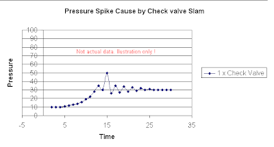
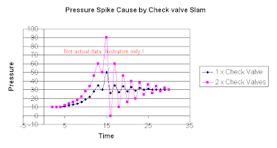
    Check valves or Non-return valves (NRV) are normally installed in piping to avoid back flow. Rotating equipment such as pump, compressor, etc will always be equipped with NRV(s) on the discharge to avoid back flow when rotating equipment is shut. Back flow creates severe surging to the rotating equipment and potentially damage the equipment. In certain process system, NRV will be employed to avoid contamination, overheating, etc due to back flow.

    Check valves or Non-return valves (NRV) is basically an automatic valve open to allow forward flow and close to against reverse flow. In principle, it split into four basic types. There are swing, dual-plate, tilting disc and lifting type. Wrong selection of check valve type can leads to operability problem, leakage and continual maintenance issue.

    Lift Check valves
    - higher pressure drop is expected.
    - equipped with small return spring to facilitate valve closure on reverse flow
    - two type of seat. hard seat for for high differential pressure sealing and resilient seat for low differential pressure sealing
    - shortest travel length. Fastest response.
    - excellent performance for low and/or pulsating flows
    - not good for fluid with particles
    - Body install horizontal with disc / piston vertically
    - Small check valve range from 1/2" to 2" lift piston type check valve
    - Prefer operate in full open position

    Minimum Recommended Line Velocity, Vmin (ft/s) = 12 SQRT (v)

    where
    v = Specific Volume of the Fluid (ft3/lb)


    Lift Check Valve

    Swing Check Valve
    - Tight sealing / shut-off
    - Low pressure drop
    - Susceptible to water hammer
    - Not good for low flow and/or pulsating flow
    - Vertical (upward flow) & horizontal installation
    - Easiest check valve to maintain
    - Prefer operate in full open position

    Swing check valves should be sized such that the flow velocity in the line is sufficient to hold the disc in the fully open position.

    Minimum Recommended Line Velocity, Vmin (ft/s) = 75 SQRT(v)

    where
    v = Specific Volume of the Fluid (ft3/lb)


    Swing Check Valve

    Dual plate Check valve
    The characteristic of dual plate check valve is pretty same as swing check valve.
    - low pressure drop
    - Not good for low flow and/or pulsating flow
    - Vertical (upward flow) & horizontal installation
    - Faster opening and closure compare to swing check valve
    - Susceptible to water hammer (lesser than Swing check valve)
    - Prefer operate in full open position


    Dual Plate Check Valve

    Tilting Disc Check Valves
    - Fast opening and closing without damage to disc and seat
    - Stable at low and pulsating flows
    - Moderate pressure drop. Lower than lifting check valve but higher than swing check valve
    - Vertical (upward) & horizontal installation
    - Moderate tight sealing
    - Prefer operate in full open position

    Minimum Recommended Line Velocity, Vmin (ft/s) = 24 sqrt (v)

    where
    v = Specific Volume of the Fluid (ft3/lb)


    Tilting Disc Check Valve


    Selection Consideration
    There are four (4) main criteria shall be considered for the selection of check valve type :
    • non-slam characteristic
    • pressure loss
    • cost
    • application
    Comparative rating for each type of check valve have been provided for these criteria (specifically first two technical criteria). These rating will be plotted on a Check Valve Comparative Selection Chart and together budget for final selection. Read more in "Design and Selection of Check Valve".

    Related Post

    Wednesday, October 1, 2008

    Basis & Tips on Setting Centrifugal Pump "Warming" Recycle Flow

    Display problem ? Click HERE

    Earlier post "Why bypass Non-Return Valve (NRV) ?" discussed the purpose of providing manual block valve across Non-Return Valve (NRV) on centrifugal pump discharge. Typical the purpose covers :
    • Pump priming
    • Pump warming
    • NRV downstream section draining


    Recommended :
    Subscribe FREE - Chemical Processing

    Now the question is focus on pump warming. What is the basis of setting this recycle flow rate ? Lets first define the purpose, how it is implemented and how to set the flow.

    Purpose
    The main purpose of the bypass line is to maintain a minimum temperature different between the pump (and associate piping ) and the pump suction fluid temperature to avoid temperature shock in the event of standby pump is started-up automatically.

    How it is implemented ?
    The bypass can be
    • fixed restriction orifice (RO) or;
    • non-return valve (NRV) with hole or;
    • globe valve
    How much flow ?
    The bypass flow rate should be sufficient to cater for :

    i) Start-up : pump and associate piping heat-up from minimum ambient to normal suction temperature within a reasonable time i.e. 2 hours
    ii) Normal operation : heat leakage via insulation during normal operation

    Tips

    Wednesday, July 23, 2008

    Flow Element (FE) Upstream or Downstream of Control Valve (CV) ?

    Display problem ? Click HERE

    Recommended :
    Subscribe FREE - Processing Magazine

    A question raised by a young engineer.

    Should a Flow element (FE) be located upstream or downstream of a control valve (CV) ?


    There is no fix rules governing the location of this flow element. It is very much subject to few factors i.e. fluid condition of the measured fluid, properties fluctuation, etc.

    a) Fluid Characteristic
    A flow element is general prefer single vapor or liquid phase as compare to two phases gas-liquid (2Ph-GL) flow. First to check is the fluid characteristic downstream of control valve. For example, liquid control valve (LCV) maintaining level of a separator. The fluid feeding the LCV is probably a liquid at bubble point. Due to static head it potentially maintain as liquid from separator outlet nozzle upto LCV. However, there is pressure drop across the LCV and 2Ph-GL flow is likely to occur downstream of LCV. Under this condition, it is always prefer to locate flow element upstream of LCV.

    Let take another example for vapor flow line. A pressure control valve (PCV) maintaining a constant saturated gas flow to downstream system i.e. fuel gas system from a separator. In the event there is large pressure drop across the PCV, Joule-Thompson (JT) effect results significant liquid formation downstream of PCV. Similarly, it is always prefer to locate flow element upstream of PCV.

    b) Pressure & Temperature Fluctuation
    Large pressure and temperature fluctuation would probably leads to properties (i.e density) changes. In general, a vapor system would experience severe changes as compare to liquid system. Thus, large pressure and temperature fluctuation may results a large deviation in properties and lead to difficulties in select a good flow element for the service. It is always prefer to locate flow element in the stream with "less" properties change .

    For example, a slug catcher is having a pressure control valve (PCV) feeding gas to booster compression system. The booster compression is targeted to maintain a constant pressure of

    Recommended :
    Subscribe FREE - Chemical Processing

    the suction scrubber. As slugcatcher pressure (upstream of PCV) may fluctuate due to slugging and pigging operation whilst the pressure (downstream of PCV) at compressor suction scrubber is rather constant, it is always prefer to locate flow element downstream of PCV. It shall be noted that there is potential liquid formation downstream of PCV which prefer to locate PCV upstream of PCV. Both rule-of-thumbs are contradicting between each and other, a process engineer shall weight both impacts to locate it at right location.

    c) Pressure Rating
    High pressure rating of flow element will be costly. Thus, it is always prefer to locate the flow element at the system with lower pressure rating, downstream of control valve.

    d) Vibration
    Pressure drop across control valve would partially convert its energy to noise and vibration. The vibration (higher intensity) would travel along fluid flow direction. Some flow element (i.e. Coriolis,Vortex) is sensitive to vibration. Vibration sensitive flow element is always advisable to locate upstream of control valve.

    A process engineer may consider above factors to locate the flow element. Apart, process engineer is always advisable to verify this subject with instrument engineer and vendor for proper location and correct flow meter type.


    Related Post

    Tuesday, May 27, 2008

    Potential Problem associate with Double NRV in Series within a Line

    Display problem ? Click HERE


    Discussion in "How to predict Check Valve Slam ?" has shown potential of surge pressure if a normal check valve is provided in the pump discharge. Nevertheless, in many design the surge pressure could be within the allowable limit of piping short term pressure spike. Thus, it is "normally" that providing a normal check valve on pump discharge does not poses any danger of pressure surge. Having said this, a proper checking should be carried out.

    One of the scenario that has been warned for many times is providing double check valves in the pumping system. With single normal check valve in the pump discharge line, the discharge may experience a short term pressure spike as shown in image below.


    In case of double check valves in the pumping system, there may be a very short time gap between the closure of both check valves. This would allow both check valves generate two pressure waves running forward and backward along the pumping system. Two waves would probably meet along the piping. Both waves' amplitude could be added or subtracted between each and other subject to wave's pattern. A severe pressure spike could be additional of two identical waves as shown in the following image.


    Above discussed about the potential of severe pressure spike in the pumping system with double check valves, however, it very subject to :

    • Shutdown valve closure time
    • Pump shutdown time and its impact on the pressure waves
    • Piping length
    • Location of the check valves
    • Check valves type and its closure time
    thus, providing double check valves does not mean severe pressure spike will definite happen. However, the potential of severe pressure spike increases as well as it associate risk. Only proper pressure surge study and review on the wave and pressure spike pattern can advise the likelihood of occurrence.

    Related Post