Showing posts with label Loss Prevention. Show all posts

Thursday, May 21, 2009

API Std 521 - Errata and Addendum Released by API

Display problem ? Click HERE

API521_errata20070621-1


This post is intended to provide supplementary information for earlier post "API Std 521 ADDENDUM, MAY 2008 - Check Out Revised Section".

Addendum May 2008
API has released the Addendum details to API Std 521. It describes in detail the modified sections compare to earlier release in 2007. You may download Addendum May 2008 from here.

Errata June 2007
For those who don't not aware the Errata in June 2007 for API Std 521 released in 2007, you may read "ERRATA - API Std 521, Pressure Relieving and Depressuring Systems" and download Errata June 2007 from here.

Related Topic

Sunday, April 12, 2009

Consider PST To Improve SIL

Display problem ? Click HERE


Many real life experiences have shown that if valves are not work or stroke for substantial period, they may failed to work (stuck at preset position) when it is on demand. This is particular critical to safety related valves i.e. Emergency shutdown (ESD) valve, blowdown (BDV) valves, pressure dump valves, etc and potentially lead catastrophe event. Valve reliability and availability is extremely critical and important in a safety system. Functional test of these valves during operation is required to main valves reliability and availability while maintaining zero / minimum production downtime. One of the testing method is on-line Partial Stroke Testing (PST), which is particular suitable for ESD valves, as well as other critical valves. PST—supplemental testing offers a method of testing the valve by moving it, typically 15-25%, and back to the original position in a short period of time in order to confirm the valve’s ability to move (not stuck in place) and its suitability for continued safety instrumented system (SIS) service.

A PST with dedicated testing interval improve a Safety Integrity Level (SIL) level of a particular SIS system. For example, a typical one-out-of-one (1oo1) ball valve with 1oo1 solenoid (Proof test, PT interval of 1 year, the average Probability of Failure on Demand (PFDavg) is about 2.25 x 10⁻², this lead to SIL of 1.65. With a PST, it improve the PFDavg to 7.36 x 10⁻³, equivalent to SIL of 2.13 with typical PFDavg Reduction of 67%. Detail refer to "Valve Failure :Not an Option". This sometime is important and useful during plant revamping and modification. For example, present SIS system demand only SIL 1 . Plant revamping and modification results SIL 2 demand. Inclusion of PST would make SIS system sufficient.

Related Topic

Wednesday, July 16, 2008

API Std 521 ADDENDUM, MAY 2008 - Check Out Revised Section

Display problem ? Click HERE

American Petroleum Petroleum (API) released the API Std 521, Pressure Relieving and Depressuring Systems early of 2007. As usual, there are some mistakes spotted in the this Standard. First errata that i received was dated June 21, 2007. Detail read here.

American Petroleum Petroleum (API) has released latest Addendum May 2008. Several sections in API Std 521 - ISO 23251 - Ed 5 - Jan 2007 - Pressure-relieving and Depressuring Systems have been updated in ADDENDUM, MAY 2008.

The updated sections are :
  • 5.15.7.4 Liquid cooling service (Partly revised)
  • 5.23 Overfilling process or surge vessel (Added)
  • 6.6.2.3 (Partly in revised)
  • 6.7 Disposal through common vent stack (Added)
  • 7.3.2.1.2 (Partly revised)
  • 7.3.2.3 Knockout drums venting to atmosphere (Added)
  • 7.3.2.4 Design details (Partly revised)
  • 7.3.4.1 Sizing (Partly revised)
  • 7.3.4.2 Design details (Partly revised)
  • Bibliography (Partly revised

Tuesday, January 15, 2008

Requirement of Overpressure Protection Device on "Final Vessel"

Display problem ? Click HERE

A question concerning requirement of overpressure protection device on "Final Vessel" was raised.
"API 14C SAC A.4.c.5 seems to indicate that a PSV is required on a pressure vessel (max pressure >5 psig) unless it is the final vessel on a flare header (i.e. Flare KO Drum). However, this implies that any other vessel venting into the flare header (e.g. Closed Drain Sump) needs a PSV to protect against blockage of the final vessel."
Recommended :
- Subscribe FREE - Processing Magazine

My personal opinion is if the connection between Closed Drain Sump and Flare KO Drum has NO internal that potentially create blockage which lead to overpressure scenario and affecting relief path, a Pressure relief device is not required on the Closed Drain Sump even though it is not the "final vessel". This is inline with the API14C SAC A.4.C.4.

The following examples show an overpressure protection device is required even though the pressure vessel is "final vessel"

a) Degassing drum with vent line and flame arrester discharge to atmosphere
This drum is a "final vessel" in the relieving path. However there is a potential of flame arrester blockage and may lead to overpressure of this drum. Thus, an overpressure protection device is required. Normally a Pressure relief valve or rupture disk is installed across the flame arrester. In this case, it is inline with the API14C SAC A.4.C.1.

b) Flare KO Drum with Flare Recovery system
In certain environment sensitive area, "zero emission" and As-Low-As-Reasonable-Practical (ALARP) principle are adopted. Those in most cases, a Flare Recovery System (FRS) will be implemented in Flare system. It could be a recovery compressor, ejector, etc. In most cases, the Flare KO Drum downstream flare line which connected to flare stack may have an on-off valve to facilitate plant maintenance. Under this case, eventhough the Flare KO Drum is the "final vessel" but an overpressure protection device (i.e. rupture disk) would be installed across the on-off valve to ensure a clear relief path. In this case, it is inline with the API14C SAC A.4.C.1.

The following examples show an overpressure protection device may NOT required even though the pressure vessel is NOT "final vessel"

a) Two drums connected together with no internal in the interconnecting pipe
As there is NO possibility existent of potential blockage on the interconnecting line and the overpressure protection device located at downstream has been designed for worst case (of two drums), an overpressure protection device is NOT required for the upstream drum. In this case, it is inline with the API14C SAC A.4.C.4.

b) Flare KO Drum with Water Seal Drum
As large relief will destroyed the water seal in the seal drum, thus there is NO possibility existent of potential blockage results overpressure scenario. Overpressure protection device is NOT required for the Flare KO drum. In this case, it is inline with the API14C SAC A.4.C.5.

If you can think of any typical example, let share it in this post.

Related Post

Wednesday, November 28, 2007

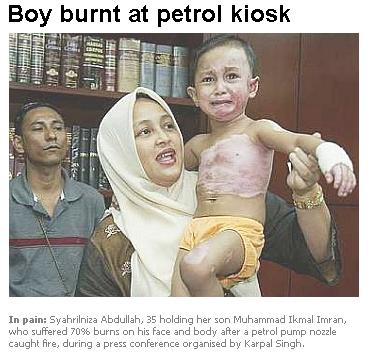
Petrol Kiosk - Some Thought and Advices...


Today i read a news here "Boy burnt at petrol kiosk". Pity the boy with 70% burnt on his face and body. The victim mentioned the following :


"As I pulled the pump nozzle out from the petrol tank, it caught fire.

"Fuel was still coming out from the burning nozzle and then adik was on fire. I threw the nozzle down and started rolling him on the ground to put out the fire."

"He said he shouted for the fire extinguisher twice but it took a while for the station staff to get it as it was locked in the office. "

From the story, i have noticed two major points
  1. fire started spontaneously without any cause.
  2. fire extinguisher is locked in the office.

CAUSES
There are many causes can lead to ignition of petrol :
  • Static charge - Some clothing may easily generate static electric when people moves. It can cause petrol fume ignited.
  • Cell phone - it carry battery and may send and receive signal without people knowing. It is another potential cause ignition. This worst could be cell phone ring when you are filling the petrol. READ more HERE.
  • Fill petrol without shutting car engine - Car engine is hot and continuously generating heat. Exhaust gas is hot may poses risk of petrol ignition.
  • Smoking - This is an obvious cause. Nobody is allowed to smoke at petrol station. Sometime the problem may came from ignorance and uneducated attendant. READ more HERE.
Of course there are other factors such as material used for petrol filling nozzle, lightning protection system, emergency shutdown system, ventilation, etc


SECURITY
Fire extinguisher is meant for emergency use but yet it store and locked in the office for security reason.
  • Ignorance - The owner and attendant ignore safety rule and regulation.
  • Uneducated - Many attendant are from non-educated group. They may not aware of safety concern

ADVICES

This has triggered me to think more as we are dealing with this on daily basis.

  • Static charge - Sometime you can not avoid generation of static charge but you can "discharge" it. Touch metal or structure before you take the petrol nozzle out from the holder. It helps to discharge (partly if not fully) the static charge.
  • Cell phone - Never take the cell phone with you in the petrol station. Keep it in the car. Also don't answer any call. If possible, switch it off.
  • Fill petrol without shutting car engine - Stop the engine.
  • Smoking - I guess this is well aware by all of us but please don't ignore.
  • Locked Fire Extinguisher - i would say make a report to authority and leave it to the enforcement team. NEVER goes back to this station again.
  • Educate those you love - You are probably serving Chemical and Process or Oil and Gas community. You are partly the "expert" in front of others. Educate others...they will believe it base on your credibility.
I guess every car user like us can do above mentioned as minimum.


Continue receive FREE stuff & Update.......Subscribe by Email OR RSS
Any comments / advices ?..........Drop it in comment field (below) or sent a private email to me...

Wednesday, November 7, 2007

Another descrepancy found in API Std 521Jan 2007

API521_errata20070621-1

In previous post, i have informed the first errata in API Std 521, edition Jan 2007. As expected more reading on this code found another discrepancy compare to previous version. This discrepancy is mainly due to REMOVAL of specific heat ratio (k) in the Mach number and Critical pressure calculation.

Equation [23] & [24] and [25] & [26] in API RP 521, 1997 (previous revision) are used to calculate the Mach number and Critical pressure of gas in the pipe.

Mach number
In imperial unit,

521_1997_Eq_23

In metric unit,

521_1997_Eq_24

Critical pressure
In imperial unit,

521_1997_Eq_25

In metric unit,

521_1997_Eq_26

After the API RP 521 is updated, similar equations used to calculate Mach number and Critical pressure has minimum modification.

Mach number
In imperial unit,

521_2007_Eq_28

In metric unit,

521_2007_Eq_27

Critical pressure
In imperial unit,

521_2007_Eq_30

In metric unit,

521_2007_Eq_29

Detail review on above equations, the specific heat capacity ratio (k) has been removed from the original equation. Is this a correction or an error ?

I have made some literature surveys and conduct some derivation works. Two main findings :

  • API R 521 1993 – No specific heat capacity ratio (k) included in the equation. However, API has included the k factor into the equation when it revised to API RP 1997. Once again, when it revised recently to 2007, the k factor has been removed again.
  • Quick derivation showed that k factor should appear in the equation.
Details refer below :

Derivation

Critical_Pressure

Based on simple derivation works, it ended-up with inclusion of k factor in the equation.

This discrepancy has been highlighted to API committee manager attention and quick response indicated equations in current edition (2007) are correct where k factor should not appear in those equations. Due to manning issue, no detail basis disclosed. Details searching do not find any supporting documents.

k factor generally range from 1.09 to 1.41 for most gases. Inverse square-root of k would range from0.84 to 0.96. Inclusion of k in the equation would probably bring down Mach number and critical pressure. Both impacts are partially balancing each and minimum impact to flowrate.

After further discussion and anaylsis, it's found that considering isothermal flow, the k factor should be omitted from the Mach number and critical pressure calculation. Details derivation may refer to "Removal of Specific Heat ratio (k) in the Mach No. & Critical Pressure Calculation".

Updated
- Nov 8, 2007
: This issue is being discussed in CheResource forum (Click HERE to view)
- Sept 28, 2008 : Post updated with omission of k factor.


Further Reading :


Continue receive FREE stuff & Update.......Subscribe by Email OR RSS
Any comments / advices ?..........Drop it in comment field (below) or sent a private email to me...

Saturday, October 20, 2007

12 Features required for Shutdown Valve (SDV)

ESD


Shutdown Valves (SDV) are common apply in oil and gas production system for safe and proper isolation purpose to minimize escalation of hazardous from one system to another system. General shutdown valve is controlled by a high integrity Emergency Shutdown System (ESDS).

A shutdown valve shall equipped with the following features :

i) Tie Shut Off (TSO)
- Zero/minimum leakage shall be expected for a device act as shutdown valve. Generally a Shutdown valve seat leakage shall pass the seat leakage testing per API 508 and/or ISO 5208.

ii) Firesafe
- shutdown valve is expected to work promptly even though it expose to external fire attacks. thus, shutdown valve body shall be fire rated according to API 607 for soft seated valve or API 6FA for API 6A & API 6D valves or BS 6755 Part 2.

iii) Fast action (From Full Open - Full Close)
- A shutdown valve shall act fast to minimize the escalation of hazards. Generally a quarter ball valve is the excellent device in quick action. As rule of thumb, shutdown valve shall be capable of begin it closing action within 10 seconds of activation, and time taken from Full open to Full Close is within 1-2 seconds per inch of shutdown valve size. However, this shall be compliant to overall safety philosophy. Proper selection and sizing of actuator to ensure above requirements are fulfilled.

iv) Minimum passing (during closing of shutdown valve)
- The feature is required to minimize the potential of overpressure of Low pressure system and spurious trip. A shutdown valve with equal% characteristic (most ball valve will have this feature. However, this shall be confirmed with valve supplier) is preferred type. With equal% characteristic, it can operate with 10% valve closure give 20% flow reduction, 20% closure give 50% closure...the closure of valve is fast and minimize inventory passing.

v) Minimum disturbance / turbulence to process fluid
- This feature is to minimize unnecessary energy lost. Reduced Bore (RB) ball valve having hole in the middle would minimize flow direction change and turbulence. Full Bore (FB) ball valve virtually like a pipe- significantly minimize energy lost.

vi) Fail-safe
- A shutdown valve actuator shall pneumatic/hydraulic fail-safe spring-return type. Generally a shutdown valve failed to close (FC). Electrical driven type shall not be used.

vii) Manual field reset
- A shutdown valve shall be reset manual at field. The operator shall ensure the system is clear and safe and reset on site. No remote reset is allowed.

viii) Clear physical indicator
- Shutdown valve shall be equipped with visible external valve position indicators to provide clear positioning and status of a shutdown valve.

ix) Position switches
Position switches shall be provided on shutdown valve to provide clear positioning and status of a shutdown valve to control room.

x) Partial Stroke Testing of Shutdown Valve
A shutdown valve in critical service e.g. Pipeline outgoing and incoming shutdown valve (ESDV) will required periodically partial stroke testing in order to maintain / increase it reliability, availability & SIL level.

xi) Accumulator
Some shutdown valve may be equipped with accumulator to facilitate valve stroking and /or reopen in the event maloperation.

xii) Second Solenoid valve
Shutdown valve in critical service may be equipped with second solenoid valve to increase reliability and availability.

Above has presented 12 features of shutdown valve. Some operating company may have their additional requirements and limitation on shutdown valve.

Related topics


Continue receive FREE stuff & Update.......Subscribe by Email OR RSS
Any comments / advices ?..........Drop it in comment field (below) or sent a private email to me...

Thursday, October 18, 2007

ERRATA - API Std 521, Pressure Relieving and Depressuring Systems

API521_errata20070621-1

American Petroleum Petroleum (API) released the API Std 521, Pressure Relieving and Depressuring Systems early of 2007. As usual, there are some mistakes spotted in the this Standard. First errata that i received was dated June 21, 2007. I am a bit outdated. Somehow, i guess there are still many engineers out there (like me...) may not aware of the release of this errata. If you are user of this standard, i strongly urge you to download this errata and make correction to your copy.


If you find anymore mistake or error in this standard, please drop a comments or sent me an Email . I will take the necessary action from there...

Related topics


Continue receive FREE stuff & Update.......Subscribe by Email OR RSS
Any comments / advices ?..........Drop it in comment field (below) or sent a private email to me...

Tuesday, September 18, 2007

Workbook for Chemical Reactor Relief System Sizing

2ph_relief

This is another of excellent workbook related to Emergency Relief System recommends to those engineer who works (design, engineering, operation) in Oil & Gas platform, Chemical & Process plant, Refinery, Chemical plant, etc. Again in particular for SAFETY & LOSS PREVENTION engineer...

WBCRRSS

Workbook for Chemical Reactor Relief System Sizing

Prepared by Janet Etchells & Jill Wilday

The workbook is to provide information on methods available for the sizing of emergency relief systems for exothermic runaway reactions in liquid-phase chemical reactions. This work mainly written for SAFETY & LOSS PREVENTION engineers who are dealing with Chemical relief with reaction and shall have good basic experiences in Chemical reaction Kinetics and fluid flow.

This workbook is available FREE for download from HSE UK.

Related topics

If you benefits from this post, buy me some sweets


Continue receive FREE stuff & Update.......Subscribe by Email OR RSS
Any comments / advices ?..........Drop it in comment field (below) or sent a private email to me...
Sunday, September 16, 2007

A must have book...Emergency Relief System Design Using DIERS Technology


This is one of excellent book that i always wanted to recommend to many of you, typically those engineer who works (design, engineering, operation) in Oil & Gas platform, Chemical & Process plant, Refinery, Chemical plant, etc.
This is a must have book specifically for those works as SAFETY & LOSS PREVENTION engineer...


Emergency Relief System Design Using DIERS


Emergency Relief System Design Using DIERS Technology
The Design Institute for Emergency Relief Systems (DIERS) Project Manual
By: Fisher, H.G.; Forrest, H.S.; Grossel, S.S.
Part of the PREFACE...
A consortium of 29 companies formed the Design Institute for EmergencyRelief Systems (DIERS) in 1976 under the auspices of the AIChE to evaluateexisting methods to design pressure relief systems for runaway reactions andto develop additional technology as needed. Approximately $1.6 million wasspent acquiring test data and documenting applicable methods for the designof emergency relief systems suitable for the discharge of two-phase vapor-liquid flow. Of particular interest was the prediction of when two-phase flowwould occur and the extent of vapor-liquid swell.
DIERS did not set out to add another two-phase flow computation procedure to the many that already existed. Rather, the goal was to identify methods that could be used to size safe, but not overly conservative, relief systems for two-phase vapor-liquid flow for flashing or frozen viscous or nonviscous fluids.
Techniques for sizing an emergency relief system for runaway reaction include:
  • Direct empirical scaling of experimental data obtained in vessels witha very lower thermal inertia.
  • Semi-theoretical graphical or analytical design methods.
  • Computer simulation of incidents and flow through relief systems.
This project manual is primarily intended
  • to provide a record of the DIERS research project.
  • to help organizations acquire, assimilate and implement the vastamount of DIERS information and technology by serving as both areference and training tool.
  • to illustrate ERS design methodology by means of selected sampleproblems.
  • to serve as a text for the AIChE/DIERS Continuing EducationCourse entitled "Emergency Relief System Design Using DIERS Technology."
If you have subscribed to KNOVEL...Click HERE
If you want to own ONE...Click HERE

Related reading

  • Requirement of overpressure protection devices on system design to PIPING code


Continue receive FREE stuff & Update.......Subscribe by Email OR RSS
Any comments / advices ?..........Drop it in comment field (below) or sent a private email to me...