Showing posts with label Separator. Show all posts

Saturday, October 4, 2008

Limiting Droplet Size For Separator Design According to GPSA Proposed K factors

Display problem ? Click HERE

Recommended :
Subscribe FREE - Processing Magazine

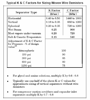
A gas liquid separator is used for bulk separation and mist eliminator i.e. vane type, mesh type, cyclone type) are used to promote liquid drop coalescence and separation from gas. Souder-Brown equation has been widely used in Oil and gas industry to size a gas liquid separator with and without mist eliminator.

Generally the K factor as proposed in GPSA has been used by many engineers. Following figure tabulate the K factor may be used for horizontal, vertical, vertical scrubber and others separator for special services.


On the other hand, there are no indication of the liquid droplet size can be removed. The following is intended to studies the limiting droplet size based on the K factor used for horizontal, vertical and vertical scrubber. In some event, it may be a useful information especially when there is droplet size limitation of downstream equipment i.e compressor.

For a droplet in free fall (gravity action), the droplet terminal velocity is as follow :


By arranging in the Souders-Brown equation :


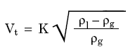
And the K factor is as follow :


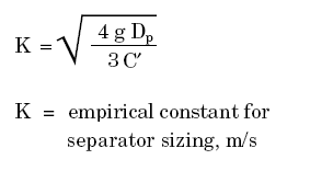
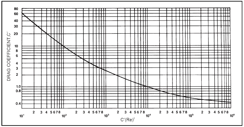
The drag coefficient (C') can be read from the following figure.


(Click to view large image)

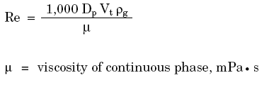
where Re is Reynolds number as follow :


Basis
For a vapor and liquid with the following condition and properties :
  • Pressure = Atmosphere
  • Temperature = 40 degC
  • Molecular Weight = 20-40
  • Compressibility factor = 0.9
  • Liquid density = 500 - 850 kg/m3
  • K factor for horizontal separator is 0.06 -0.075 m/s
  • K factor for vertical separator is 0.025-0.055 m/s
  • K factor for vertical scrubber is 0.018 -0.039 m/s
Results
The limiting liquid droplet size are

Horizontal separator without mist eliminator : 350 -540 micron
Vertical separator without mist eliminator : 160 -400 micron
Vertical scrubber without mist eliminator : 125-290 micron


Related Topic

Saturday, September 27, 2008

Oil - Water Separator for Household

Display problem ? Click HERE

In oil and gas production, formation water and condensed water present in oil and gas. These water cause hydrate formation in offshore transfer pipeline, severe slugging, corrosion, etc. They are contaminant shall be removed to meet the oil and gas specification. Water separated from oil and gas is normally contaminated with oil which can be in dispersed and diluted form. If the contaminated water is separated from a 2 phase or 3 phase separator , the oil contaminant level can be as high as 3000 ppmw. This level is far higher than the acceptable level of 30-40 ppmw. The contaminated water required further treatment.

Recommended :
Subscribe FREE - Processing Magazine

Contaminated water treatment are complicated. There are physical separation which includes solid-liquid separation, liquid-liquid separation, diluted component removal, etc as well as chemical treatment and biological treatment. In the physical separation, the normal technology used are hydrocyclone, corrugated plate pack unit, floatation unit, etc.

Similarly, the wastewater from daily usage i.e. wash water from kitchen is contaminated with oil. The oil and water may be separated with above mentioned unit. Following video clips presented a basic plate pack unit which separated oil from water before the water is discharged to public drainage. The separation principle is basically promote oil droplet coalescence in plate pack follow by gravity separation. The oil level in treated water can reach 20 ppmw level and possibly discharge directly to public drainage network (subject to local rules). The separated oil can be collected and storage in a storage tank and ready to be pumped to waste treatment plant for extraction.


Oil water separation process (video clip)


Oil water pre-module (video clip)


Oil water separation box (video clip)

Related Topic

Tuesday, March 25, 2008

Factors you shall Consider for Separator with Boot

Display problem ? Click HERE


A vapor-liquid-liquid separation is rather common in offshore oil and gas facilities. Generally separator with boot is preferred for low heavy liquid percentage in the mixtures. What are the factors you shall consider so that you select a separator with boot.

i) Material cost for separator with boot compare to separator with weir is lower. This is in generally perspective but there are exceptional case. It is pretty hard to provides a simple rule of thumb in general for all services. Nevertheless, Bill Svrcek et. al (1994) has indicated that a boot may be selected if the heavy phase is 15-20wt%. This could be a quick goby for a pre-selection during early engineering phase, however, it is always encourage optimization.

ii) Boot fabrication required hole drilling at the bottom of horizontal vessel, installation of reinforcement ring around the the boot-vessel connection and additional weldings around the connection. This signify the fabrication is rather complicated and increases the fabrication cost. Thus, combination of material and fabrication cost, total cost for a separator with boot may be higher than a separator with internal weir.

iii) Overall separator size would be one of the factor to be considered. It is not much cost benefits by selecting a separator with boot for rather small separator.

iv) Cost for space or overhead. Separator with boot may results small vessel and save installation cross section area. This potentially save cost on the foot print. However, it impose additional cost for overhead. For onshore facilities, normally head room is not a an issue in most cases, however head room could be major cost factor for offshore installation.

v) Separator with boot will result lesser inventory in the separator and this will reduce risk (inventory associated) in this installation.

vi) Separator with boot is having lesser weight (material and inventory) and this will reduce cost for vessel support. This is pretty attractive for large separator.

vii) For light and heavy liquid separation with very similar density e.g. heavy crude (typical ~900 kg/m3) and produced water (~1030 kg/m3), it could leads interface controllability problem if insufficient margin is provided. Separator with boot would increases the vertical length and increases the controllability of interface.

viii) Normally there is a optimum diameter for Separator with boot installation (i.e. boot diameter is 2/3 maximum of separator diameter). The limitation of the boot diameter over separator diameter may be a major determining factor. One process engineer shall not ignore this mechanical constraints.

ix) As there is boot diameter limitation, increase boot length is the only direction to increase interface controllability. Extended boot length is not really cost effective as all other cost factor increase.

x) Boot installation will results more vessel cutting and more welding compare to internal weir. This will induce higher risk to be managed.

xi) Boot once it is constructed, it is fixed and you have no way to revamp if you wish to. However, a weir installation still can be changed (especially removable weir) after it's fabricated or in operation. The weir height can be changed/adjusted as operator wish. This increases flexibility on made-good for uncertain fluid characteristic.

Continue receive FREE stuff & Update.......Subscribe by Email OR RSS
Any comments / advices ?..........Drop it in comment field (below) or send a private email to me...

Tuesday, January 22, 2008

Quick Understanding & Estimation of Mist Eliminator in Gas-Liquid Separator

Display problem ? Click HERE


There are many young design engineer will experience or has experienced gas - liquid separator sizing. In most cases, a mist eliminator is used to trap small liquid droplet entrained in the gas. Now the engineer may experience difficulties in answering the following questions :
  1. What type of mist eliminator (e.g. mesh pads, vane pack, etc) should be used ?
  2. What are the advantages and disadvantages of mesh pad and vane pack ?
  3. How mesh pads and vane pack trap liquid droplet ?
  4. What is the liquid capture efficiency of mesh pad and vane pack ?
  5. How droplet size, mesh strand diameter, gas velocity, liquid density, gas density, gas viscosity, mesh pad/vane pack design affecting liquid capture efficiency ?
  6. What is the limit of mesh pad compare to vane pack ?
  7. How do i size mesh pad or vane pack mist eliminator ?
  8. What are the geometry and installation requirement of separator with mist eliminator ?
  9. ...etc
First advice to young engineer is read this great article "MESH & VANE Mist Eliminator" by AMISTCO. Basically, this article most of your questions.

Although this article may assist you in determining the type of mist eliminator, dimension, mist eliminator thickness, gas flow area, etc using a recommended design Souders-Brown vapor load factor (K), however there are still many other type of mist eliminator (MistFix insertion mist eliminator, double-pocket vane pack, which potentially result better removal efficiency and cost effective as compare to ordinary mesh pads and vane pack. In addition, the graph is tested with air-water mixture, it may have some deviation with actual process fluid. The deviation could be insignificant or very significant.

You may use above proposed method for PRELIMINARY sizing in order to get a quick separator dimensioning, the detail selection and calculation shall be conducted by mist eliminator supplier with their proprietary graph and correction parameters.

In many real world examples, the mist eliminator thickness would be in the range of 4"-6". Thus, you may use this PRELIMINARY thickness in quick separator dimensioning.

Related Topic

Continue receive FREE stuff & Update.......Subscribe by Email OR RSS
Any comments / advices ?..........Drop it in comment field (below) or send a private email to me...

Sunday, October 7, 2007

Slugging & Slugcatcher

In oil & gas field development, interfiled pipelines widely used to transfer well fluid from Satellite wellhead (SW) to Center Processing Platform (CPP) for pretreatment, conditioning and processing. Partial conditioned gas and partial stabilized condensate will then transfer to onshore plant via pipeline for further processing. Byproduct or waste such as produced water, Mercury, sand, etc are generally removed at CPP. Produced and Mercury will be injected back to reservoir for proper disposal. Collected sand which contaminated with hydrocarbon, mercury, etc will be send to onshore for treatment prior to sand filled.

Slugging
Partial conditioned gas and partial stabilized condensate travel through long distance pipeline will experience frictional loss and heat loss to ambient. These results change in equilibrium state and lead to condensate formation for partial conditioned gas and flashing in partial stabilized condensate. Two phase gas-liquid flow along pipeline will leads to unavoidable non-stable operation e.g. slugging flow.

Hydrodynamic Slugs
Shift in equilibrium results liquid formation or flashing and subsequently leads to slug formation, this type of slugs called Hydrodynamic slugs. Apart, there are other way / operation will results slugs formation.

Terrain Induced Slugs
Slug caused by accumulation and periodic pushing of liquid column along pipeline is called Terrain Induced Slugs. This kind of slug generally observed in severe undulation pipeline and low flow operation.

Flow Induced Slugs
Low flow operation leads to liquid accumulation in the seabed. During production ramp-up, high gas flow force liquid holdup in the pipeline towards receiving facilities. Big slug may form if improper operation of ramp-up activities.

Operational Induced Slugs
Pipeline inspection and maintenance is part of the frequent activity for any pipeline. Pigging will be the general activity to carry pipeline inspection and removal of liquid holdup, debris, sand, mercury, etc accumulated in the pipeline. Severe slugging may occurred during pigging if the pigging activity is improperly managed.

As slug approaching receiving facilities, slug size will grow. Large slug arrived at first receiver will seriously overload the liquid handling capacity and may leads to tripping of receiving facilities. Increase liquid handling capacity to handing intermittent large liquid flow may not be cost effective. Thus generally the first receiver will be designed to temporary store the intermittent slug and it will be treated after the slugging period. This receiver generally called Slug catcher.

Slug catcher is a device normally to carry bulk separation and to temporary store big slugs. There are few types of slug catchers have been designed. The following is a listing of types of slug catcher :

a) Horizontal separator type
b) Vertical separator type
c) Finger type
d) Slug Stabilizer type

Type (a) & (b) are essentially same as conventional horizontal and vertical slug catcher but with built-in slug handling capability.


Horizontal type


Vertical type

Following images show typical finger type and slug stabilizer type slug catcher :

Finger_SC


Continue receive FREE stuff & Update.......Subscribe by Email OR RSS
Any comments / advices ?..........Drop it in comment field (below) or sent a private email to me...

Friday, May 4, 2007

KnitMesh...Good Articles on Mist eliminator still available FREE...


KnitMesh...a subsidiary of SULZER Chemtech today...Its separations technology business has been acquired by Sulzer Chemtech since Decr 13th, 2006.
Entire acquisition process may be completed by first quarter of 2007. PRESS release notes... KnitMesh website is still exist today...and there are quite a lot of good articles available FREE for download... We are not sure if this site will continue to exist...I would encourage you to visit this site now and get these good articles before it is demolished...You need to register prior to any download...
Automotive

Air Bag Filters
Anti-Vibration Sound Attenuating & Heat Shield Components
Catalytic Convertor Mesh Wraps
Catalytic Convertor Seals
Engine Breathers
Exhaust Decoupling Rings & Mesh Sleeves
Separation Rings
Silencer and Muffler Packings
Spacer Rings

WebWorm