Showing posts with label Corrosion Resistance Material. Show all posts

Saturday, March 27, 2010

Brief About NACE MR 0175

Sulfide -stress cracking is basically a hydrogen-embrittlement phenomenon .Atomic hydrogen enters the steel to cause cracking. The hydrogen is generated on the surface of the steel because of a corrosion reaction. Iron reacts with h2s to form iron sulfide and hydrogen .This hydrogen is generated in atomic form on the steel surface ,where it can either combine to form molecular hydrogen and leave the surface as bubbles or diffuse into steel .This latter process may result in hydrogen embrittlement .Hydrogen sulfide prevents hydrogen recombination & thus promote entry of atomic hydrogen into steel .It is important to note that water must be present for this mechanism to occur ;without it SSC will not be observed ,because the ionization of the hydrogen sulfide is required.

Following is a lecture presentation on NACE Standard MR0175  - Petroleum and Natural Gas Industries – Materials for use in H2S-containing Environments in Oil and Gas Production.
 

Download


Related Post

Saturday, March 20, 2010

NACE MR0103 versus MR0175

NACE MR0103 "Materials Resistant to Sulfide Stress Cracking in Corrosive Petroleum Refining Environments" was developed by Task Group 231 to provide a standard set of requirements for materials used in sour petroleum refinery equipment. In the past, NACE MR01752, "Sulfide Stress Cracking Resistant Metallic Materials for Oilfield Equipment", was frequently referenced for this equipment, even though refinery applications were outside the scope of MR0175. The process used to develop MR0103 is described, followed by a review of the requirements in the standard accompanied by highlights of the differences between MR0103 and the previous and current versions of MR0175.

An Overview of NACE International Standard MR0103 and Comparison with MR0175 


Click here to download the article


A presentation has been prepared by the author which further summary the differences. You may download via the following link : Download Presentation Handout

Thanks to Don BUSH, Jeff BROWN & Keith LEWIS


Related Post

Tuesday, February 2, 2010

Facts about Erosion & Erosion-Corrosion

Recommended :
- Subscribe FREE - Chemical Engineering
- Tips on Succession in FREE Subscription

Wet vapor potential condense and form liquid droplet (mist flow), vapor at high velocity will drag the droplet and flow approximately same speed as vapor. Whenever vapor with liquid droplet flow  change in direction at elbow, bend, tee, valve, reducer, etc, liquid droplet will high density tends to impinge on the pipe wall and results erosion. Droplet impingement on pipe wall results erosion is commonly occur in Mist flow.

As liquid condensation increase, liquid droplet coalesce and accumulate and slowdown due to increase in mass and shearing force near wall. Vapor flows in swirling pattern in pipe creates centrifugal force pushing  liquid stick to the pipe and moving forward. Swirling liquid moving forward at reasonable high velocity will results erosion on pipe wall and common occur in Annular flow.

Further increase in liquid flow will further slow down liquid movement in the pipe compare to vapor flow. Swirling flow and vapor dragging liquid surface tends to create liquid slug and restrict vapor in the pipe.  Vapor at high velocity behind slug will accelerate slug and potentially hammering on pipe wall, elbow, bend, reducer,etc. Severe vibration, noise level and erosion will occurs in Slugging flow.

Mist flow, annular flow and slugging flow erode pipe in different ways and results different level of erosion. Many researchers and experts have spend their time and effort in deriving the erosion rate for two phase flow phenomenon and derive criteria in designing a pipe in two phase flow.

Droplet Erosion velocity threshold
As discussed in "Erosion & Erosion - Corrosion", erosivity is highly affected by particle/droplet velocity. High particle/droplet velocity results high momentum on impacting surface and leads to higher successive erosion. It is commonly understood that Erosion Rate (ER) is proportional to particle impacting Velocity raised to the power of n where n may range from 2 to 3 for ductile material (e.g. stainless steel) and possibly upto 6 for brittle material (e.g. some plastic material). Many researchers have conducted experiments and derived the Droplet Erosion velocity threshold for solid free fluid.

Droplet Erosion velocity threshold (VE ) for solid-free fluid
  • DNV RP O501, VE = 70 ~ 80 m/s
  • Salama & Venkatesh, VE = 26 ~ 118 m/s
  • Shinogaya, VE = 80 m/s for Aluminum, 100 m/s for pure iron, 110 m/s for SS
  • Svedeman & Arnold, VE = 30 m/s
Looking at above results, there is no one common range for the Droplet Erosion velocity threshold (VE ) for solid-free fluid due to complexity of two phase gas liquid flow.


Erosion model & Erosion Velocity Criteria
There are many models have been studied and proposed :

  • API RP 14E Erosion model
  • Salama & Venkatesh model
  • Salama 2000 model
  • DNV ERBEND model
  • AEA Harwell model
  • Tulsa SPPS model
Among all, API 14E erosion model is one of the earliest model being used in designing two phase gas liquid flow. Many others models have evolved from this basic model.

API RP 14E recommends

VE = C / Sqrt (mixture density)

VE in ft/s
mixture density in lb/ft3

C =100 for solid free corrosive and continuous operation service
C =125 for solid free corrosive and intermittent operation service
C =150 to 200 for solid free non-corrosive or CI controlled and continuous operation service
C =250 for solid free non-corrosive or CI controlled and intermittent operation service

Today, general perception is that API RP 14E recommendation is highly conservative. Many experiments have demonstrated this perception and recommends higher C value to be used.

Salama & Venkatesh have similar model and recommends :
C = 300 for solid free flow.


Salama recommends :
C = 400 for solid free non-corrosive fluid
C = 300 for solid free corrosive fluid


NORSOK standard P-001 (Ed. 5) recommends :
Wellhead flow-lines, production manifolds, process headers and other lines made of steel and transporting two-phase or multiphase flow, have a velocity limitation. When determining the maximum allowable velocity, factors such as piping geometry, well-stream composition, sand particle (or proppant) contamination and the material choice for the line shall be considered.

As a guideline, the maximum allowable velocity can be calculated by:

VE = C / Sqrt (mixture density)

where
VE  in ft/s
mixture density in lb/ft3 
C =  150

  • Non corrosive service - For non corrosive well-stream and for corrosion resistant pipe materials the velocity should be limited to maximum 25 m/s if the well-stream includes only small amounts of sand or proppants (typical less than 30 mg sand/liter in the mixed flow).
  • Corrosive service - For carbon steel (CS) piping systems the corrosion rate often limits the life time. With increased flow velocity the corrosion rate tend to increase due to increased shear forces and increased mass transfer. The flow velocity should be restricted to maximum 10 m/s to limit the erosion of the protective layer of corrosion products and reduce the risk for a corrosion inhibitor film break down.
Again, above shows that there is no one common Erosion velocity limit for for solid-free fluid due to complexity of two phase gas liquid flow.


Solid / Sand Present in Fluid
With the present of sand in single and/or two phase gas liquid  flow further increase it complexity :

NORSOK standard P-001 (Ed. 5) recommends :
  • Particle erosion in non corrosive service - For well-stream contaminated with particles the maximum allowable velocity shall be calculated based on sand concentration, piping geometry (bend radius, restrictions) pipe size and added erosion allowance. For the calculation of maximum velocity and life time specialised computer programmes are available and should be employed.
  • Liquid flow with presents of sand, maximum allowable velocity (VMax ) are :
    • 5 m/s for CS
    • 7 m/s for SS/Titanium


NORSOK standard M-001, section 4.2.2.... recommends :
If sand production and/or particles from well cleaning and squeeze operations are expected, an erosion evaluation shall be carried out. The evaluation should be based on DNV RP-O-501

Salama recommends

VE = D * Sqrt (mix den) / [20 * Sqrt (W)] 

where
VE = Erosion velocity limit (m/s)
D = pipe internal diameter (mm)
W = sand production rate (kg/day)
Mix den = Mixture density in (kg/m3)

Author has worked projects for many well-known oil and gas companies e.g. SHELL, EXXONMOBIL, TOTAL, BP, etc. All companies philosophy in erosion and erosion-corrosion and criteria in designing two phase gas liquid and sand-laden fluid are different.

Some Facts from Literature / Studies
Following are facts related to erosion :
  • Material such as tungsten carbides, coating, ceramic, etc commonly formed part of valve internal component are vulnerable to erosion.
  • Particle impinging surface at varies angle results different erosion impact. Maximum impact is particle impacting perpendicular to surface
  • Corrosion inhibitor (CI) form layer at internal pipe isolating / minimizing corrosive fluid contacts with corrosion susceptible material. Erosion due to fluid and particle impingement on CI layer potentially remove this protective layer. Commonly maximum velocity to avoid erosion of CI layer is 20 m/s. Some special CI can tolerate upto 50 m/s
  • Sand production with downhole sand control, sand concentration at 1st receiver typically contains 1 to 50 ppmw of sand concentration. Past experience may reach 100 ppmw.
  • A well produce 5 to 10 lb/day of sand is typically regarded as "Sand-free production".
  • "Nominal solid-free" production is common defined as less than approx. 3 gram-per-m3 for liquid or less than 0.1 lb/mmscf for gas
  • Well with downhold sand control may contains sand sizes typically range from 50 to 100 micron. Those without downhole sand control may range from 50 to 500 micron
  • Erosion rate is commonly proportional to particle impact velocity into power of a factor range from 2 to 3 for steel.
  • Higher fluid viscosity and density increase drag effect and "holding" capacity. Viscous and dense fluid tends to reduce particle impacting on surface
  • Typical sand particle density is 2600 kg/m3
  • API RP14E recommendation is conservative for solid free liquid service from erosion aspect. However, it potentially under-estimate solid free gas/vapor service (subject to droplet erosion)
  • Rich amine potential expose erosion and cavitation effect when it is flashed from high pressure to lower pressure. Low threshold velocity should be used e.g. 1-2 m/s.
  • Elbow and tee are most vulnerable to erosion compare to others component
  • In gas and condensate production with present of solid / sand particle, API 14E has no clear recommendation to account for erosion rate.
Above is meant to provide some information for those engineers dealing in erosion. The complexity lead to many opinion and recommendation. What about yours in previous/present projects ???


Related Topics

Friday, January 23, 2009

Crevice Corrosion Engineering Guide Software for Stainless Steels

Display problem ? Click HERE


Recommended :Earlier post "Crevice Corrosion Mechanism & Prevention" has briefly discussed mechanism of crevice corrosion and its prevention. As discussed, one of the preventive measures is to select correct material to resist crevice corrosion. Stainless Steel (SS) is known to resist to general corrosion by forming a thin, protective oxide film on it external surface, SS still susceptible to localized corrosion i.e. Chloride stress corrosion cracking (CSCC), crevice corrosion, pitting corrosion, etc once this protective film is partly damage. Stainless steel once expose to water (present of Chloride) with temperature higher than 60 degC, CSCC is potentially occurred. On the other hand, temperature lower than 60 degC, crevice and pitting corrosion is potentially occurred.

There are different grade of Stainless Steel i.e. SS304, SS316, S31803, S32205, etc. How Chloride [Cl] concentration, Sulfate [SO4] concentration, pH level, temperature, oxygen level, etc affecting crevice corrosion for different Stainless Steel ?


The Crevice Corrosion Engineering Guide for Stainless Steels (CCEG) is a program available FREE to check type of Stainless Steel susceptible to crevice corrosion in water under particular conditions and impurities. The CCEG is a program with predictive mathematical model of crevice corrosion to assist with the selection of stainless steels for use in chloride and sulphate containing waters, including sea water. It was jointly developed by Nickel Development Institute (NiDI) and Sheffield Testing Laboratories Ltd.


Application Range
This program has been developed with the following application range :
  • Fluid : Water
  • Operating temperature : 5 - 85 degC
  • Chloride [Cl] concentration : 1-30,000 ppm
  • Sulphate [SO4] concentration : 0-10,000 ppm
  • Total Dissolved Solids (TDS) concentration : 0 - 65000 ppm or mg/L
  • * Can be calculated base on 1.65 [Cl] + [SO4]
  • Alkalinity : 0 - 10000 mg/L (as concentration of CaCO3 in mg/L)
  • Hardness : 0 - 20000 mg/L (as concentration of CaCO3 in mg/L)
  • pH : 5 - 9
Stainless Steel Grade Can be Checked
The program will check for following material :
  • S30400
  • S31600
  • S31700
  • S31803
  • S32205
  • N08904
  • 6% Mo SS

Example
Let take a water with following parameters :
  • Chloride (ppm) : 1000
  • Sulphate (ppm) : 100
  • Hardness (as CaCO3 mg/L) : 100
  • Alkalinity (As CaCO3 mg/L) : 100
  • TDS (mg/L) : 1798
  • pH : 7
  • Temp (C) : 25
  • Oxygen level (ppm) : 7
CCEG predict corrosion will not occur with S31803 however corrosion will initiate in days with S31600.

Download : Click here to download the program (1.17 MB).
Source : Nickel Development Institute (NiDI)

Related Topics

Saturday, January 17, 2009

Crevice Corrosion Mechanism & Prevention

Display problem ? Click HERE

Recommended :
- Subscribe FREE - Energy Biz
- Tips on Succession in FREE Subscription

Crevice is location /area / space where normal fluid has less contact and access with it. Typical example of crevice are gaps between parts, space between gaskets and bolt, inside seals, inside cracks due to external impact or scratches, spaces filled with deposits, plastic paper lay on the metal plate, etc. In crevice, the environment is different than area expose to normal fluid. For example, gasket with bolt. Bolt surface expose to atmosphere is oxygen rich while wet air trapped between bolt and gasket is stagnant and with limited oxygen. Localized corrosion occur in the crevice is called crevice corrosion.

Crevice Corrosion Example
Following is an example of crevice corrosion at pipe support.


Crevice corrosion is pretty similar to pitting corrosion as discussed in "Pitting Corrosion - Mechanism & Prevention".


Mechanism
A metal surface with gasket at shown above will potentially experience crevice corrosion. Oxygen rich fluid enters crevice between gasket and metal surface.

- Genenal Oxidation Corroion
Normal corrosion (general oxidation corrosion) will occur through the metal surface outside and inside the crevice. As oxygen in trapped fluid consumed oxygen, environment within crevice is deoxygenated (low in oxygen level) increases the potential difference between crevice environment and oxygen rich environment.

Metal (E.g. FE) surface (expose to atmosphere) is oxygen rich will becomes the cathode whilst the metal surface in the crevice (gasket contacted area) is low in oxygen level will becomes anode. This form a complete circuit where metal at the crevice (FE) will be ionized to release electron (e) and form ion Ferum (FE2+), this electron will travel to the metal surface expose to atmosphere to react with Oxygen (O2) and water (H2O) to form ion hydroxides (OH-). Ion Ferum (FE2+) will react with ion hydroxides (OH-) to form Ferum Oxide (Fe2O3) which typically a brown rust.

- Increases Acidity in Crevice Environment
The ions FE2+ formed potentially hydrolyze water (H2O) in tapped fluid and produced positive ion (i.e. H+) and FE (corrosion product). The corrosion product will further block the movement of trapped fluid and increase the corrosion potential. The H+ will further increase the acidity of the trapped fluid and this severely increases corrosivity of trapped fluid.

- Other Corrosion i.e. CSCC
Production of ion positive (H+) will also attract negative ions i.e Chlorides, Sulfates, etc outside crevice travel into the trapped fluid in crevice, accumulation of these negative ions will potentially results Chloride and Sulfate associated corrosion such Chloride stress corrosion cracking (CSCC).


Preventive measures
There are several preventive measures to minimize crevice corrosion.

i) Avoid / minimize crevices during design stage i.e. keep junction points as wide open as possible.
ii) Avoid / Minimise crevices during fabrication i.e. smooth weld
iii) Avoid / minimize solution get into crevice i.e. greasing bolt / nut
iv) Use high resistance material (high PRE material)
v) Avoid / Minimise crevices during operation. Scale settled on metal surface will form "crevice" and trapped fluid. Routine cleaning to remove scale is one of the effective way to minimise crevices.
vi) Avoid/ Minimize objects i.e plastic bag put on metal surface.
vii) External coating

Related Topics

Wednesday, January 14, 2009

Stainless Steel and It Selection Training Module

Display problem ? Click HERE


Stainless steel is one type of material commonly used in oil & gas, refinery, petrochemical, pharmaceutical industries. Stainless steel is a material does not stain and corrosion resistance to many fluids. Stainless steel is rather "soft" and infact it is a cavitation resistance material. This has been discussed in "Stainless Steel SS316 resist to CAVITATION ?".

Recommended :
- Subscribe FREE - Processing Magazine
- Tips on Succession in FREE Subscription

Although Stainless steel is corrosion resistance to many corrosive fluids by formation of protective oxide film, it is still susceptible to pitting corrosion, one of the most destructive forms of corrosion which potentially cause equipment failures on perforation / penetration as discussed in "Pitting Corrosion - Mechanism & Prevention".

Beside pitting corrosion, stainless steel also susceptible to Chloride Stress Corrosion Cracking (CSCC) as discussed in "Chloride Stress Corrosion Cracking & Use correct MOC for seawater service". CSCC is initiation and propagation of cracks in a metal or alloy under tensile stresses and a corrosive environment contains Chloride compounds. Once the crack is initiated, it will propagate rapidly and potentially lead to catastrophic failure. There are more discussion on stainless steel can be found here.

Dr. David Jenkinson, Director of Nickel Institute has produced a series online training modules on "An Introduction to Selection of Stainless Steels for Corrosion Resistance". The online training modules are in audio format which can be read while listen to the explanation. Visual plus audio will quickly assist engineers in understanding the contents.

Click here to begin learning Stainless Steel and It Selection.

Following are complete listing of training module for Stainless Steel and It Selection.

01 - Disclaimer
02 - Module Abstract
03 - Module Information
04 - Chemical Symbols
05 - What Will We Cover?
06 - What Will We Cover? - What is Stainless Steel?
07 - How Stainless Steel Works
08 - Chromium is the Basic Building Block of Stainless Steels
09 - Damage to the Protective Oxide Film
10 - Penetration of the Protective Oxide Film
11 - Corrosion of Embedded Iron in a Stainless Steel Pipe Bend
12 - The protective passive film can be damaged mechanically or chemically in various ways.
13 - What Will We Cover? - Effect of Alloying Additions
14 - Effect of Alloying Additions
15 - 1. Corrosion Resistance
16 - Effect of Alloying Elements on Corrorsion Resistance - Chromium
17 - Effect of Chromium on Atmospheric Corrosion of Steels
18 - Pitting Resistance Equivalent Number (PRE)
19 - Effect of Alloying Elements on Corrosion Resistance - Nickel
20 - Addition of Nickel
21 - Nickel Provides Resistance to Reducing Chemicals
22 - Effect of Alloying Elements on Corrorsion Resistance - Molybdenum
23 - Effect of Alloying Elements on Corrorsion Resistance - Nitrogen
24 - Effect of Alloying Elements on Corrorsion Resistance - Carbon
25 - Hibernia Oil Production Platform
26 - 2. Crystal Structure
27 - Ferritic Stainless Steels
28 - Adding Nickel to Stainless Steels
29 - Austenitic Stainless Steel
30 - Duplex Stainless Steels
31 - List of Ferrite & Austenite Formers
32 - When Choosing a Stainless Steel
33 - What Will We Cover? - Families of Stainless Steels
34 - Families of Stainless Steels
35 - Ferritic Stainless Steels
36 - Typical Compositions of Common Stainless Steels
37 - Type 409 is hte most widely used ferritic stainless steel.
38 - Proprietary Grades
39 - Dishwashers
40 - Stainless Steel Refrigerators
41 - Hot Water Tank
42 - Austenitic Stainless Steels
43 - Typical Compositions of Common Stainless Steels
44 - Domestic Kitchen Sink
45 - Parliament House, Canberra, Australia
46 - Type 304 Stainless Steel Beer Kegs
47 - Chemical Plant
48 - Frederick R. Weisman Art Museum
49 - Wet Electrostatic Precipitator
50 - Duplex Stainless Steels
51 - Typical Compositions of Common Stainless Steels
52 - Type 316LN Stainless Steel - Example
53 - Pressurized Peroxide Reactor
54 - Stainless Steel Meat Racks
55 - Elevator Tower
56 - Families of Stainless Steels
57 - Martensitic Stainless Steels
58 - Typical Compositions of Common Stainless Steels
59 - Stainless Steel Products - Examples
60 - Martensitic Stainless Steel Blades
61 - Precipitation Hardening (PH) Stainless Steels
62 - Typical Compositions of Common Stainless Steels
63 - High Strength S45000 Precipitation Hardening Stainless Steel
64 - What Will We Cover? - Maximizing Corrosion Resistance
65 - Corrosion of Carbon Steel
66 - General Corrosion
67 - Localized Corrosion
68 - Pitting
69 - Once it gets started, pitting is difficult to stop and to repair.
70 - PRE Numbers for Some Ferritic, Austenitic & Duplex Grades
71 - Pitting Corrosion - Effect of Temperature and Chloride Level
72 - Crevice Corrosion
73 - Crevice Corrosion - Example
74 - Chloride Stress Corrosion Cracking (SCC)
75 - Chloride Stress Corrosion Cracking - Example
76 - Copson Curve
77 - Chloride Stress Corrosion Cracking - Effect of Temperature and Chloride Level
78 - What Will We Cover? - High Performance Stainless Steels
79 - High Performance Stainless Steels
80 - Pitting and Crevice Corrosion Resistance
81 - Three Families of High Performance Stainless Steels
82 - PRE Numbers for Some Ferritic, Austenitic & Duplex Grades
83 - Immersed in Seawater Without Cathodic Protection
84 - Heat Exchanger
85 - Flexible Hosing
86 - Heat Exchanger for Aggressive Chloride Service
87 - Zeron 100 Fittings
88 - Condenser Tubes
89 - What Will We Cover? - Nickel Alloys
90 - More Resistant Alloys
91 - Nickel Alloys
92 - Alloy C-276
93 - Summary

Further Reading

Sunday, January 11, 2009

Determine Corrosion Allownace (CA) with Corrosion Inhibition (CI)

Display problem ? Click HERE

Recommended :
- Subscribe FREE - Processing Magazine
- Tips on Succession in FREE Subscription

Earlier posts "Quick Estimation of CO2 Corrosion Rate", "CO2 Corrosion Rate Estimation Using M-506 Model" and "CO2 Corrosion Using Freecorp Model", the DeWaard Milliam model, Norsok M-506 model and FREECORP models have been introduced. All these corrosion estimation models are available FREE for all. Corrosion allowance (CA) is provided in pipeline / piping to cater for required design life. Low corrosion rate (CR) will require low CA. For high CR, higher CA is provided. In many events, corrosion inhibitor (CI) is injected into corrosive in order to reduce CR. Although low CA with CI injection, CI would incur high operation cost. Thus, a life cycle cost (LCC) study will require to be conducted to determining he cost effective option in provision of normal material with CA plus CI or Corrosion Resistance Material (CRA).

For the CA plus CI injection option, one of the factor shall be taken into account in determining CA is the availability of corrosion inhibition. There are many events would lead to corrosion inhibition unavailable i.e. maintenance, nonscheduled trip, deficiency of inhibition, unexpected flow, etc. Following is a simple method in determining the CA by consideration of Availability.

CA = t x [ICR x Av + UCR x (1 - Av)]

where :
CA = Corrosion rate
t = Design life
ICR = Inhibited Corrosion Rate
UCR = Uninhibited Corrosion Rate

Example :
A pipeline is design for 25 years, the corrosion rate is about 3 mm/year. High corrosion allowance (25 x 3 = 75 mm) is required and this has lead to injection of Corrosion Inhibition (CI) to reduce the corrosion rate to 0.3 mm/year. It is expected the availability of corrosion inhibition facilties is about 90%. Calculate CA required with CI injection.

t = 25
ICR = 0.3 mm / year
UCR = 3 mm / year
Av = 90%

CA = t x [ICR x Av + UCR x (1 - Av)]
CA = 25 x [0.3 x 90% + 3.0 x (1-90%)]
CA = 14.25 mm

Required CA is 14.25 mm.


A simple Corrosion Allowance Calculator is ready for download.
Download Corrosion Allowance Calculator (Excel).

Related Post

Sunday, June 29, 2008

Material for High H2SO4 Concentration and High Temperature & Pressure

Display problem ? Click HERE

Recommended :
Subscribe FREE - Plant Services

In earlier post "FAYF - Acid Solution Storage", Carbon Steel (CS) may be used for concentrated Sulfuric acid (H2SO4) at ambient temperature. However, diluted H2SO4 may severely corrodes CS. Non-metal material (PVC, PFA, FEP, PTFE) may be used for concentrated and diluted H2SO4 solution. Nevertheless, these materials lose it strength at high temperature and high pressure operation. Using non-metal material may not be cost effective at high temperature and high pressure design.

Thus for high temperature and high pressure operation, exotic material Zirconium and its alloy may be considered.

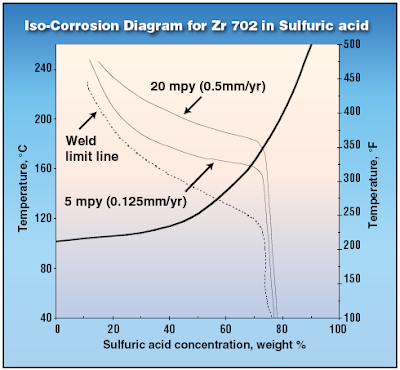
Zirconium has excellent corrosion resistance in all concentrations of sulfuric acid up to 70% and well above boiling.


Zirconium Limitation and its work-around...
H2SO4 concentration exceeded 55%, there will be preferential corrosion attack at weld. WIth H2SO4 concentration exceeded 65%, there may be Sulfide Stress Corrosion Cracking (SSCC) in Zirconium. Thus, stress-relief anneal (heat treatment) should be conducted to avoid above mentioned preferential corrosion and SSCC. However, In the presence of fluoride ions, Zirconium should not be used with sulfuric acid.

For H2SO4 concentration exceeded 70%, other material such as Tantalum may be considered. Tantalum can take any H2SO4 concentration with temperature upto 200 degC.

Read more details explanation in


Note :
*This article is only available FREE to Chemical Engineering Magazine registered user.
Login required.
Registration FREE (Click HERE).
** Download immediately as article available FREE within short period (JUNE 2008 only)
*** Found lost link or unable to download, may contact me...

RELATED POST

Tuesday, June 24, 2008

Why Rupture (RD) Upstream of Pressure Relief Valve (PRV) ?

Display problem ? Click HERE


Recommended :
Subscribe FREE - Chemical Processing

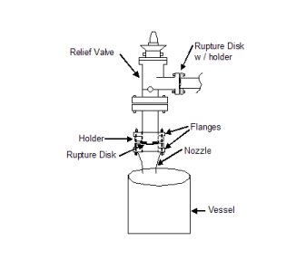
Two main group of pressure relief devices are accepted as ultimate or final safeguarding device against overpressure protection of pressure contained equipments. There are reclosable type (pressure relief valve) and non-reclosable type (rupture disc). Both type of devices have been used in different application with their special reclosable and non-reclosable characteristic. Nevertheless, in some application, rupture disc (RD) and pressure relief valve (PRV) are use in combination. They have been applied such that RD is located upstream of PRV.


What is the main purpose and advantages by placing RD upstream of PRV ?

To answer this question, it can be answered from several aspects :
  • Safety
  • Environment
  • Cost
Plugging PRV inlet flow path (Safety)
Equipment with fluid contain particles, solid, substances may freeze, crystallize & polymerize, etc, these substances potential stay and stick to the nozzle and PSV inlet pipe. It potentially lead to reduced flow path area and reduce flowing capacity of the relief flow path. Reduced flow would lead to overpressure and catastrophe event. Apart, reduced flow path increases inlet line frictional lose (more than 3% of set pressure) and potentially cause PSV chattering and damage. Providing RD upstream of PRV would avoid these substances accumulate at the inlet nozzle and pipes.

Prevent Opening of PRV (Safety)
As solid substance can contacts with PRV disc and seat, it may stick to the disc and seat and solidify. Sticked substance may prevent PRV from opening or increases force (pressure) to open the PRV. This potentially cause internal pressure exceeded Maximum Allowable Working Pressure (MAWP) of the protected equipment and lead to catastrophe event. Providing RD upstream of PRV would avoid these substances contact with PRV's disc and seat.

PRV "Slow" Action (Safety)
This has been discussed in "Tube Rupture : Pressure Relief Valve (PSV) or Rupture Disk (RD) ?". In the event liquid in Low Pressure Side (LPS), sudden tube rupture may generate a huge surge pressure to the LPS within a mili-second and results the intermittent peak pressure exceeded design pressure of LPS, pressure relief valve (PRV) is NOT recommended in this case. Pressure relief valve is known to be a “slow acting device”, it may NOT response fast enough to relieve pressure. Thus, a rupture disk which known as “quick acting device” is always recommended in this case.


PRV Passing / Leaks (Environment & Health)
PRV passing and leaks is one of the common phenomenon and difficult to avoid. Continuous leaking toxic substances to atmosphere would lead to pollution (environment issue) and contact with human (health issue). Providing a RD could prevent continuous leakage.

Corrosive Fluid Corrode PRV (Capital Cost)
Corrosive fluid contact with PRV would required a Corrosion Resistance Material (CRA) PRV. It will be less expensive with corrosion resisted (CRA) RD and non-corrosion resisted (non-CRA) PRV.

Longer Overhaul/Maintenance Period (Maintenance Cost)
As fluid is not in contact with PRV (with RD upstream), the PRV is considered rather "clean" and "new". Thus, a longer period of between each Overhaul/maintenance can be extended. This indirectly reduce maintenance cost.

Extended PRV Life Span (Maintenance Cost)
Similar to above, fluid is not in contact with PRV, the PRV is considered rather "clean" and "new" and life span of PRV is extended.

Wednesday, June 18, 2008

What are the concerns related to H2S ?

Display problem ? Click HERE


High demand in energy source i.e. petroleum, LNG, etc leads to high pricing of these sources. This has given addition incentive to explore those sour field. Sour field being Oil or gas contains high H2S which potentially lead to material cracking.

What are the problem or concerns related to H2S ?

Toxic
First and far most important concern related to H2S is high toxicity. Human exposure of H2S at high concentration within a short period could lead to fatal.

Environment
H2S release to atmosphere would mix and dissolve in moisture and form acid rain which is corrosive and create human health concerns.


Corrosion & Stress Cracking
i) Sulphide Stress Corrosion Cracking (SSCC)
H2S dissolved in water to form weak acid promote corrosion and form free hydrogen. Free Hydrogen will penetrate the metal, reduce ductility of metal and potentially lead to stress failure below it yield stress, results Sulphide Stress Corrosion Cracking (SSCC).

Sulfide stress corrosion cracking (SSCC) is cracking of metal involving corrosion and tensile stress (residual and/or applied) in the presence of water and H2S. SSC is a form of hydrogen stress cracking (HSC) and involves embrittlement of the metal by atomic hydrogen that is produced by acid corrosion on the metal surface. Hydrogen uptake is promoted in the presence of sulfides. The atomic hydrogen can diffuse into the metal, reduce ductility and increase susceptibility to cracking. High strength metallic materials and hard weld zones are prone to SSC. (Source : NACE MR 0175)

Apart from SSCC, H2S also cause other cracking, including stress corrosion cracking (SCC), hydrogen-induced cracking (HIC) and stepwise cracking (SWC), stress-oriented hydrogen induced cracking (SOHIC), soft zone cracking (SZC) and galvanically induced hydrogen stress cracking.

Hydrogen Stress Cracking (HSC)
HSC refer to cracking that results from the presence of hydrogen in a metal and tensile stress (residual and/or applied). HSC describes cracking in metals that are not sensitive to SSC but which may be embrittled by hydrogen when galvanically coupled, as the cathode, to another metal that is corroding actively as an anode. The term galvanically induced HSC has been used for this mechanism of cracking.*

Stress Corrosion Cracking (SCC)
SCC refer to cracking of metal involving anodic processes of localized corrosion and tensile stress (residual and/or applied) in the presence of water and H2S. Chlorides and/or oxidants and elevated temperature can increase the susceptibility of metals to this mechanism of attacks. *

For Chlorides stress corrosion cracking (CSCC), read more in Chloride Stress Corrosion Cracking & Use correct MOC for seawater service

Hydrogen-Induced Cracking (HIC)
HIC refer to planar cracking that occurs in carbon and low alloy steels when atomic hydrogen diffuses into the steel and then combines to form molecular hydrogen at trap sites. Cracking results from the pressurization of trap sites by hydrogen. No externally applied stress is needed for the formation of hydrogen-induced cracks. Trap sites capable of causing HIC are commonly found in steels with high impurity levels that have a high density of planar inclusions and/or regions of anomalous microstructure (e.g. banding) produced by segregation of impurity and alloying elements in the steel. This form of hydrogen-induced cracking is not related to welding.*

Stepwise Cracking (SWC)
SWC refer to cracking that connects hydrogen-induced cracks on adjacent planes in a steel. This term describes the crack appearance. The linking of hydrogen-induced cracks to produce stepwise cracking is dependent upon local strain between the cracks and embrittlement of the surrounding steel by dissolved hydrogen. HIC/SWC is usually associated with low-strength plate steels used in the production of pipes and vessels.*

Stress-Oriented Hydrogen-Induced Cracking (SOHIC)
SOHIC refer to staggered small cracks formed approximately perpendicular to the principal stress (residual or applied) resulting in a “ladderlike” crack array linking (sometimes small) pre-existing HIC cracks. The mode of cracking can be categorized as SSC caused by a combination of external stress and the local strain around hydrogen-induced cracks. SOHIC is related to SSC and HIC/SWC. It has been observed in parent material of longitudinally welded pipe and in the heat-affected zone (HAZ) of welds in pressure vessels. SOHIC is a relatively uncommon phenomenon usually associated with low-strength ferritic pipe and pressure vessel steels.*

Soft Zone Cracking (SZC)
SZC refer to form of SSC that may occur when a steel contains a local “soft zone” of low yield strength material. Under service loads, soft zones may yield and accumulate plastic strain locally, increasing the SSC susceptibility to cracking of an otherwise SSC-resistant material. Such soft zones are typically associated with welds in carbon steels.*

* Source : NACE MR 0175 - ISO 15156

Related Post

Tuesday, June 3, 2008

Stainless Steel SS316 resist to CAVITATION ?

Display problem ? Click HERE


Stainless Steel (i.e. SS316) is "soft" compare to other material e.g Cast Iron, Duplex stainless steel, etc. due to it has high ductility. However, high ductility of stainless steel make a good material resist cavitation.

How stainless steel against cavitation ?

The main reason is due to work-hardening property of Stainless Steel. Hammering a SS316 strip would lead to surface work-hardens and difficult to change the shape.

Similar phenomenon occurs when microjet impacting on the surface of stainless steel and caused the Stainless steel work-hardens, and increase resistance to further cavitation.

SS316 resists cavitation about 10-15 times better than cast iron whilst CA6NM (modified SS316) is roughly 2-3 times more resistant to cavitation as compared to SS 316.

Related Topic

Wednesday, December 12, 2007

Why don't consider coating your exchanger tubes ?


Many Shell and Tube heat exchangers are provided in Chemical and Process plant for heat exchanging, heat recovery and integration for energy saving. There are many issues associate with Shell and tube heat exchanger such as corrosion, fouling & scaling, heat transfer efficiency drop, cleaning and maintenance, etc.


One of the way to minimize and avoid above mentioned issues is applying protective coating on the tubes. The benefits are :
  • CORROSION - Coating avoid corrosive contact with tube material and avoid corrosion. Extra corrosion allowance or corrosion resistance material is required. If severe corrosion occur, retubing may be required.
  • FOULING & SCALING - Coating avoid sticky fluid contact with tube material and stay as fouling & scale.
  • HEAT TRANSFER EFFICIENCY - Fouling & scaling will reduce heat transfer efficiency and more heat transfer area required. This will increases the heat exchanger capital investment.
  • CLEANING & MAINTENANCE - Fouled heat exchanger shall be shutdown for cleaning and maintenance. In some event, chemical cleaning may be required. This increases heat exchanger operating and maintenance cost and also increases downtime and reduce plant availability.
  • COST EFFECTIVENESS - In some configuration and operating condition, coating compare to corrosion resistance material, coating may turn out to be very cost effective.

Curran International (CI) is one of the heat exchanger tubing coating service provider. Edward Curran from CI has published an article in Chemical Processing.com.


On the other hand, there are disadvantages for coating. One of the major issue is the reliability of coating stay in tubing without dropping-off. Lost of coating layer may put the heat exchanger in unsafe operation without operator awareness and potentially lead to catastrophic consequence. This is an major issue alway debate till no conclusion and receive a lot of challenges.

What do you think about coating tubing ? Is any of your heat exchanger tubing coated ? Why not share you experience here ?

Related Topic


Continue receive FREE stuff & Update.......Subscribe by Email OR RSS
Any comments / advices ?..........Drop it in comment field (below) or sent a private email to me...

Thursday, September 20, 2007

Design fault in Hydrogen Attack of Residue Hydrodesulfurrization


In earlier post,<< High Temperature Hydrogen Attack in metal & alloy>> there are some discussion on how hydrogen attack in metal & alloy is initiated and a paper in recent activities in hydrogen attack.

How many of you have ever heard accident caused by High Temperature Hydrogen Attack in metal & alloy ? How severe is this attack ?

By chance, i found an accident of High Temperature Hydrogen attack on Carbon Steel piping at the outlet of a Pressure Relief Valve. This accident happened in the Residue Hydrodesulfurization unit in Japan. This accident has killed five (5) operators and injured three (3) operators.


High temperature gas contain Hydrogen is compressed and fed to furnace and reactor. Heating and reaction taken place in the furnace and reactor and hot product is fed to a separator. Pressure Relief Valve protecting compressor is bypassed the furnace and reactor and connected to downstream of furnace and reactor. Generally the is no flow passing the Pressure Relief Valve discharge and is expected the discharge piping is always under low temperature. Those High temperature hydrogen attack is not expected in the Pressure Relief Valve discharge piping and design has not considered it.

After the incident, investigation has reported that the burst piping is caused by High Temperature Hydrogen Attack. How the piping is exposed high temperature and how the hydrogen can get into this piping ?

If you review details drawing in figure 4 in the report, you will find that the piping burst at the location closed to the main pipe. During normal operation, hot gas is flowing through the main pipe and main pipe is heated to high temperature. Hot main pipe will transmit heat to the branch from Pressure relief Valve with conduction effect. Temperature is gradual reduced with distance from the branch tie-in.

In the event compressor is overpressure, pressure relief valve popped will release high temperature gas with hydrogen rich in it. Whenever it passing through the pipe, hot piping metal will pick-up the hydrogen, react with Carbon in the piping and form Methane and this will weaken the hot carbon steel piping.

One note has not been addressed is that there is residue hydrogen gas in the product line. This continuously expose the branch with hydrogen. Hydrogen pick-up activity is continues during normal operation.

Lesson here is never under-estimated Hydrogen attack in metal and alloy. Whenever dealing with hydrogen, special attention shall be taken for those non- continuous operating lines.

Related reading


Continue receive FREE stuff & Update.......Subscribe by Email OR RSS
Any comments / advices ?..........Drop it in comment field (below) or sent a private email to me...