Showing posts with label Heat Exchanger. Show all posts

Monday, August 23, 2010

Brazed Aluminium Heat Exchanger (BAHX) Standard

A brazed aluminium plate-fin heat exchanger consists of a block (core) of alternating layers (passages) of corrugated fins. The layers are separated from each other by parting sheets and sealed along the edges by means of side bars, and are provided with inlet and outlet ports for the streams. The block is bounded by cap sheets at the top and bottom. An illustration of a multi-stream plate-fin heat exchanger is shown below image.


The Standards of the Brazed Aluminium Plate-Fin Heat Exchanger Manufacturers' Association (ALPEMA) is the result of the work by a technical committee of all the Members to meet the objective of the Association to promote the quality and safe use of this type of heat exchanger. The Standards contain all relevant information for the specification, procurement, and use of Brazed Aluminium Plate-Fin Heat Exchangers. The First Edition was published in 1994, has proved extremely successful and popular. Changes in the industry, experience with using the Standards and feedback from users has resulted released of Second Edition. Now the Standards of the Brazed Aluminium Plate-Fin Heat Exchanger Manufacturers' Association (ALPEMA) is available FREE for download.


Related Post

Sunday, July 11, 2010

PFHE & CWHE Comparison in LNG Plant

Main Cryogenic heat exchanger (MCHE) is one of key equipment in natural gas liquefaction (LNG) plant. MCHE used in liquefaction of natural gas having some special characteristic :
  • Intensive/excessive heat exchange (230 - 400 kW / ton LNG)
  • Complex heat transfer - Heat transfer from one (or several) very high pressure natural gas stream to one or several low pressure refrigerant streams
  • Thermal stress/shock - Very large temperature difference between inlet (40 degC) and outlet temperature (-162 degC)
  • Operate at very low temperature (-162 degC)
  • High heat transfer efficiency - Very low temperature approach (2-3 degC) to maximize heat transfer per unit area
  • Involve phase change and risk of phase separation and proper distribution
  • High risk of leakage and safety related issue
  • High risk of blockage/plugging
  • Lightweight & easy transportation


Two type of compact MCHE widely used in LNG plant. There are Plate-Fin Heat Exchanger and Coil (Spiral) Wound Heat Exchanger. Below images are typical CWHE and PFHE.


CWHE

CWHE is coils/tubes wound in spiral around a mandrel and all coils / tubes are contains within a pressure vessel. Multiple coils/tube in bundle can be flew simultaneously within the pressure vessel.


PFHE

PFHE is corrugated or serrated plate stacking on each and others to creates cross and/or counter flow paths to allow heat transfer of multiple fluids.

Although both type of HE have been widely used, CWHE and PFHE have their own special features and advantages. Below are simple comparison between both CWHE and PFHE.

FeaturesCoil Wound Heat Exchanger (CWHE) Plate-Fin Heat Exchanger (PFHE)
CompactnessCompact Extremely compact
Heat Transfer area (m²/m³) 20 - 300300 - 1400
Flow type in heat transferCross-CounterCross and/or Counter
Flow patternSingle and/or two phasesSingle and/or two phases
Flow streamsSingle or MultipleSingle or Multiple
ConfigurationSingle or multiple coil-in-vessel unitMultiple plate-fin units
Flow path8-12mm tube1-2 mm flow channel
Risk of contaminant built-upLess (smooth tube surface)More (multiple channels / cores increase crevices)
Risk of PluggingLowerHigher
Thermal Stress ResistanceHigher (tube robustness & flexibility)Lower (plate fin inflexible)
Risk of Thermal StressLowerHigher
Gas/Liquid distributionLess mal-distribution (single flow channel)Higher mal-distribution (multiple unit in parallel)
Risk of Thermal ShockLowerHigher (mal-distribution lead to imbalance heat transfer)
SafetyLower (tube contains within pressurized vessel - natural gas leaks to vessel)Higher (natural gas leaks to atmosphere)
AvailabilityHigher (production continue with some tube leaks until next shutdown)Lower (immediate production shutdown when leaks occur)
TransportationReasonable easy (with multiple bundles)Easy (Multiple units)
MaterialAluminum / Stainless Steel / Carbon Steel / Others AlloyAluminum
CostHigherLower


Related Post

Free "Introduction to Heat Transfer" Ebook

Recommended :

It is often found necessary to transfer heat form hot to cold fluids by means of heat exchangers. there is wide variety of equipment available for this purpose, although in this Engineering Design Guide discussion is restricted to the more common types (other heat exchangers being mentioned only in passing). The very important aspect of removing heat from a primary source, such as a fired heater or the fuel elements of a nuclear reactor, also falls outside the scope of this guide. Although sufficient information is provided to enable the reader to understand and deal with simple heat transfer problems, this text to a large extend serve as an introduction to the more specialized books to which reference is made...


This FREE HEAT TRANSFER ebook discusses on several topics related to heat transfer and heat exchange. It content cover the general problem of heat exchange, analysis of heat conduction, convective heat transfer, thermal radiation heat transfer, mass transfer, etc

Download
Source : http://www.hts.org.uk/
Thanks to D. Butterworth

Related Post

Sunday, March 7, 2010

Cooling Tower Performance & Plume Abatement


Cooling Tower is widely used in Refinery and PetroChemical Industry to remove heat from process system and rejected heat into atmospheric which act as natural heat sink. In earlier post "Useful Documents Related to Cooling Tower", there are many useful articles related to Cooling Tower. This post will includes two additional articles from SPX Cooling Technologies.


Cooling Tower Performance Basic Theory and Practice (New)
A cooling tower is a specialized heat exchanger in which two fluids (air and water) are brought into direct contact with each other to affect the transfer of heat.


ClearSky™ Plume Abatement Brochure (New)
Marley ClearSky™ Plume Abatement System is a ground-breaking approach to the reduction of cooling plumes. Employing leading-edge technology, not only does ClearSky provide the proven performance you need—including design flexibility—but it can also lower installation and operating costs. In fact ClearSky has simply the best value proposition in plume abatement—it can even be installed into existing cooling tower applications, negating the need for complete system replacement. 

More articles in "Useful Documents Related to Cooling Tower" ...

Related Topic

Wednesday, February 11, 2009

Tantalum S&T HEX vs Carbon Block HEX...

Display problem ? Click HERE


Recommended :
- Subscribe FREE - Chemical Processing
- Tips on Succession in FREE Subscription


Steel picklers have traditionally used carbon block heat exchangers to heat their shallow tank high turbulence pickle baths. The multi-gasketed designs and fragile nature of graphite heat exchangers still require continuous maintenance and repair which results in expensive downtime and spare parts. This has forced the industry to look for alternatives. The use of metal shell and tube heat exchangers virtually eliminates all of the problems associated with carbon block heat exchangers.

As claimed, some of the benefits of metal shell and tube heat exchangers are :
  • Cost competitive with Carbon Block Heat Exchangers
  • Easily retrofittable into existing equipment footprint
  • Elimination of downtime due to equipment failure
  • No spare parts to keep in inventory
  • Superior corrosion resistance
  • High heat transfer
  • High steam pressures to reduce required surface area
  • Fully welded metal design eliminates breakage during handling, installation and operation
  • Elimination of acid leaks into steam condensate
Typical comparison of a Carbon block HEX to a tantalum S&T HEX

Description
Carbon block HEXTantalum S&T HEX
Heat Input(BTU)1,000,0001,000,000
Steam Pressure (PSI)7575
Typical Overall U
(BTU/hrft2.F)
250 650
Surface Area Required
(Sq. Ft.)
29*11.2*
Inventory of Spare
Parts Required
YES NO
Fully Welded
Metal Design
NOYES

Basic heat transfer equation used to calculate required surface area.
*Tantalum heat exchanger surface area required does not take into consideration using a higher pressure steam.

Interested in detail ? Click HERE
Download
Source : www.titanmf.com

Related Post

Saturday, February 7, 2009

Control Valve at Inlet or Outlet of HEX ?

Display problem ? Click HERE


Product fluid in reactor involve exothermic process is commonly hot. It is then sent to distillation and separation system for catalyst and raw material recovery. Separated product is then cooled by plant wide Cooling Water (CW) before it is sent to storage tank. The product temperature will have to be maintained.

How this temperature is controlled ?


Temperature Control Methods

There are several ways to maintain the product temperature :

(i) Provide a product bypass across the Cooler, control valves on Product bypass line and Outlet line (Split range control) with fixed CW flowrate
(ii) Provide a CW bypass across the Cooler, control valves on CW bypass line and CW inlet to Cooler with full product flow across cooler
(iii) Provide a CW bypass across the Cooler, control valves on CW bypass line and CW outlet to Cooler with full product flow across cooler
(iv) Provide a Control valve at the Cooler inlet with full product flow across cooler
(v) Provide a Control valve at the Cooler outlet with full product flow across cooler

Generally the product flow is fixed by operator based on production plan and the product flow shall not be controlled. Thus, it is always not recommended to provide a control valve at the inlet and outlet of product line for product temperature control.

Disturbance of CW Network Balance
Cooling water is in a network supplying to many heat exchanger through out the plant for cooling purpose. It is normally supplied by a set of centrifugal pump. As centrifugal pump head will be affected flow across, any changes in the CW demand will affect the CW balance in network. This will further affect the pressure in the network and hence the CW flow into other heat exchangers. Thus, it is always recommended not to throttle the CW flow as much as possible to avoid CW balance.

Scaling
Throttling CW flow into heat exchanger would potential lead to low CW flow into heat exchanger, high film temperature at on CW side and promote scaling. The option (ii) and (iii) are always recommended IF throttling on CW side is chosen.

Potential affecting Production
Controlling product fluid temperature with product bypass across the Cooler, control valves on Product bypass line and Outlet line (Split range control) and fixed CW flowrate (option i) is one of the common way in temperature control for product cooling. As it minimize the impact to CW network. Nevertheless, there is still concern about manipulating product fluid or mal-operation (controller failure) of control valves would potentially lead to production lost, the option (ii) and (iii) are always the recommended option.

CW Pressurise or Non-Pressurise
Option (ii) and (iv) compare to option (iii) and (v), the difference is the location of main CW line control valve (either at the inlet or the outlet). Providing a control valve at the outlet will have the following advantages :

a) Maintain high pressure in the heat exchanger and higher pressure will results higher heat transfer

b) CW at high pressure will minimise potential of boiling

c) CW at high pressure will minimise potential release of dissolved gases in CW , trap in heat exchanger and reduce heat transfer

d) In event of Control valve failure (failed to full close position), not further Cooling. CW in the heat exchanger will be heated and potentially lead to heat exchanger overpresure due to thermal expansion and/or boiling. The CW will be relieved via Pressure Relief Device provided on the heat exchanger. Providing control valve at the outlet would allow continue CW feeding into the heat exchanger, this minimise the potential of sudden temperature increase and cause heat exchanger due to thermal shock. The downside is release CW into disposal network.

Considering above advantages, it is always recommended to provide control valve on CW line at the outlet IF throttling CW side is chooses.

CONTROLLING SHELL AND TUBE EXCHANGERS
"Controlling Shell & Tube Heat Exchanger", an excellent article by Walter Driedger discussed about all type of control schemes around heat exchanger. Check out.

Related Topic

Thursday, February 5, 2009

Control Around Heat Exchanger

Display problem ? Click HERE


CONTROLLING SHELL AND TUBE EXCHANGERS
Shell and tube heat exchangers are among the more confusing pieces of equipment for the process control engineer. The principle of operation is simple enough: Two fluids of different temperatures are brought into close contact but are prevented from mixing by a physical barrier. The temperature of the two fluids will tend to equalize. By arranging counter-current flow it is possible for the temperature at the outlet of each fluid to approach the temperature at the inlet of the other. The heat contents are simply exchanged from one fluid to the other and vice versa. No energy is added or removed.

Since the heat demands of the process are not constant, and the heat content of the two fluids is not constant either, the heat exchanger must be designed for the worst case and must be controlled to make it operate at the particular rate required by the process at every moment in time. The heat exchanger itself is not constant. Its characteristic changes with time. The most common change is a reduction in the heat transfer rate due to fouling of the surfaces. Exchangers are initially oversized to allow for the fouling which gradually builds up during use until the exchanger is no longer capable of performing its duty. Once it has been cleaned it is again oversized...

"Controlling Shell & Tube Heat Exchanger", an excellent article by Walter Driedger discussed about all type of control schemes around heat exchanger. You may download here.

Download
Source : www.driedger.ca

Related Topic

Wednesday, August 20, 2008

Few Tips on Energy Efficient & Recovery

Display problem ? Click HERE


As the price of electricity, natural gas and other fossil fuels continues to climb, chemical processors are more closely examining high-temperature operations and heat-transfer systems to see if more efficiency can be had. In many cases
it can, and, as a result, heat-transfer projects are not only justifiable, but downright attractive.

There was a dialog among a few heat exchanger specialist from Alfa Laval, Paul Muller, Exergy LLC, etc. The dialog mainly discussed on strategy to improve heat transfer efficiency, heat recovery and efficient process control during this high energy price arena.

A few tips have been present :
  • The energy crisis results high prices all of the time shorten paybacks. Energy efficient is one of the way to minimize cost
  • Energy efficient heat transfer equipment such as Plate Heat exchanger, Gasketed Heat exchanger, Bonded Heat exchanger, etc is one of the option.
  • For a service using Shell & Tube (S&T), the overall heat transfer coefficient (HTC) is around 300 Btu/h ft2°F. However, the overall heat transfer coefficient (HTC) for a compact heat exchanger can be improved 3-4 times (~1000 to 12000 Btu/h ft2°F).
  • With lower overall heat transfer coefficient, this may translate into less space, smaller installation and handling cost. Capital cost may not be low as the fabrication cost for compact heat exchanger is high.
  • Gasketed Heat exchanger good for maintenance. However shall take additional attention on the compatibility between gasket and fluid.
  • All welded or Bonded heat exchanger may be considered if there is gasket & fluid compatible problem
  • For laminar flow, heat transfer rate is only the function of fluid thermal conductivity. Operate heat transfer equipment at lamina flow during turndown could significantly reduce it heat transfer rate
  • Compact heat exchanger promote turbulence. High turbulence increase heat transfer rate and reduce fouling (read more)
  • Thus plant releasing hot exhaust gas from burner, boiler, gas turbine, etc to atmosphere may take the opportunity to recover heat
  • Improve temperature control in process system would reduce energy usage
Download details discussion...Registered CE subscriber only
Not a CE subscriber... click here to subscribe FREE Chemical Engineering (CE)

Related Topic

Friday, April 4, 2008

How to consider Area for Relieving flow in Plate Heat Exchanger Internal Failure

Display problem ? Click HERE

A Shell & Tube heat exchanger potentially expose to the risk of internal failure results a complete tube rupture. Read Criteria for Requirement of Pressure Relief Device for Tube Rupture for criteria lead to tube rupture. In determining the required relieving flow rate, API Std 521 - ISO 23251, Fifth edition, Jan 2007, "Pressure-relieving and Depressuring Systems ", section 5.19.3. can be referred
5.19.3 Determining the required relief flow rate
In practice, an internal failure can vary from a pinhole leak to a complete tube rupture. For the purpose of determining the required relieving flow rate for the steady-state approach, the following basis should be used.

a) The tube failure is a sharp break in one tube.
b) The tube failure is assumed to occur at the back side of the tubesheet.
c) The high-pressure fluid is assumed to flow both through the tube stub remaining in the tubesheet and through the other longer section of tube.

A simplifying assumption of two orifices may also be used in lieu of the above method, since this produces a larger relief flow rate than the above approach of a long open tube and tube stub.
How to determine a maximum area for relieving flow in Plate & Frame heat exchanger (PHE) which is having rather different structure in construction ?

A Plate & Frame Heat Exchanger is constructed by putting many corrugated plates together likes a sandwich and allowing fluids passing the channels (opening area between plate). Hot and cold will take the channel between plate in "sandwich" format e.g. first channel is hot fluid in upward direction, second channel is cold fluid in downward direction, third channel is hot fluid in upward direction again, etc... Detail may refer HERE...

Cross sectional view of the plate heat exchanger is as follow.


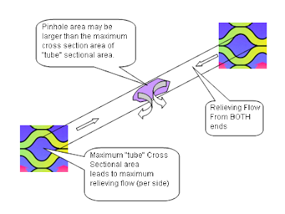
Refer to following image.


From above limit, maximum relief flow shall be taken as equivalent to the leakage rate through a pinhole of a cross sectional area equal to twice the maximum area of a "tube" cross sectional area. This maximum "tube" cross sectional area may be advised by PHE vendor.

Related Topic

Continue receive FREE stuff & Update.......Subscribe by Email OR RSS
Any comments / advices ?..........Drop it in comment field (below) or send a private email to me...

Sunday, March 30, 2008

A few means to avoid hydrate formation downstream of air cooler...

Display problem ? Click HERE

In site experiencing summer and winter, normally the air cooler (heat transfer area) will be designed based on maximum ambient air temperature during summer. However, ambient air temperature will drop significantly during winter and those air cooler handling wet gas (saturated with water vapor or free water found in vapor phase) will potentially experience hydrate formation as the fluid temperature cooled below the hydrate formation temperature of fluid. How the tackle this kind of issue ?

There are few practical means to tackle hydrate formation downstream of air cooler which only occur during winter.

(i) Manual shutdown of fans
Install a temperature transmitter with low temperature alarm (LAL) downstream of air cooler outlet to monitor the fluid temperature. In the event the fluid temperature decrease as the ambient temperature is dropped, once it reaches the LAL set point and triggers alarm, operator may stop some motors (fan) to reduce forced air flow and reduced heat removal from air cooler. As this action required operator attention and uncertainties in fluid composition, it is recommended to provide more margin on the set point i.e 10 degC above hydrate formation temperature.

(ii) Auto-Control Air Flow
Install a temperature transmitter with low temperature alarm (LAL) downstream of air cooler and Variable Speed Drive for air cooler motors so that the vapor temperature is maintained at some margin (e.g. 5 degC) above hydrate formation temperature. In this way, the fluid temperature is maintained by controlling air flow (controlling motor speed) via air cooler tubes,hence the heat removal from process fluid.

You may aware that other than above mentioned benefit, there are other benefits as discussed in Variable Frequency Drive (VFD) helps in Many Aspects (click here).

VSD control is one the effective means in controlling air cooler outlet temperature. There are other means of controlling the temperature as discussed in Air Cooled Heat Exchanger Control using Variable Pitch Fans.

(iii) Inject Hydrate Inhibitor upstream of Air cooler
This is one of the common method in controlling hydrate formation. However, the continuous consumption of hydrate inhibitor could lead to high life cycle cost of the plant and may not be attractive at all. Apart, there are other problems associate with hydrate inhibitor (i.e. methanol, MEG, TEG, etc). If methanol is used, it will stay in vapor form and follow the vapor to downstream processing facilities. Methanol is not easy to be removed from the gas phase and methanol-water mixtures when it is knocked out as liquid in cold section. If MEG /MEG is used, it potentially poison downstream equipment such as membrane and form a contaminant in gas phase.

Apart, some may consider to provide a bypass around the air cooler so that hot fluid from upstream of air cooler warm with fluid outlet of air cooler and expecting mixture is above hydrate formation temperature. This will ONLY help in fluid downstream of mixing, but hydrate formation still occur upstream of mixing point. Hot bypass DOES NOT HELPS !

Another aspect one shall remember is mal-distribution of air flow within the air cooler tube bundle would lead to some tubes experience higher air flow compare to other tubes and results fluid in some tubes experience temperature lower than hydrate formation temperature. Hence, whenever the hydrate temperature is lower than minimum ambient temperature, mal-distribution of air flow within tube bundle shall be analyzed in detail. Moreover if the fluid entering air cooler is two phase gas liquid flow, phase separation at the distribution header would even worsen above scenario.

Related Post

Continue receive FREE stuff & Update.......Subscribe by Email OR RSS
Any comments / advices ?..........Drop it in comment field (below) or send a private email to me...

Friday, March 14, 2008

Cooling Tower Thermal Design Manual


If you are professional engineer, fresh engineer or student and working or interested in COOLING TOWER thermal design, "Cooling Tower Thermal Design Manual" one of the FREE e-manual that you shall not miss. It available FREE for browsing and provided by Daeil Aqua, a specialist company in cooling tower design.

This engineering book was prepared for educating the cooling tower engineers of a company in Taiwan. So, this deals with a very specific subjects, which were never written as of now. I prepared the documents so that the engineers can easily understand the cooling tower theory and can make the design program by themselves through the actual examples. All were run on MS Excel and you will see this new approach in computerizing the cooling tower thermal design. You can download all the examples through this homepage.

The major concern during I study the cooling tower theory was how to computerize the cooling tower theory from the calculation of NTU to the cooling tower performance analysis. If you read this book carefully, you can make any cooling tower design programs by yourself.

Again, this will be a first issue releasing the actual engineering approach of cooling tower with the examples in the world. If any questions on this issue, please send your mail to me.
It consists of 22 chapters and listed as follow :
Preface to Fifth Edition
Chapter 1. Psychrometrics
Chapter 2. Heat & Mass Transfer Fundamentals
Chapter 3. Tower Demand & Characteristic Curves
Chapter 4. Cooling Tower Performance Variables
Chapter 5. Consideration of By-pass Wall Water
Chapter 6. Pressure Drops in Cooling Tower
Chapter 7. Velocity Recovery at Fan Stack
Chapter 8. Motor Power Sizing
Chapter 9. Fan Components Sizing
Chapter 10. Air-Water Distribution System Design
Chapter 11. Recirculation of Exit Air
Chapter 12. Evaporation
Chapter 13. Estimation of Actual Cold Water Temperature
Chapter 14. Determination of L/G
Chapter 15. Compare of Tower Performance at Sea Level and Altitude
Chapter 16. Evaluation of Tower Performance at Design Off Design
Chapter 17. Plotting of Tower Performance Curves
Chapter 18. Estimation of Air Flow at No-Load Condition
Chapter 19. Determination of Pumping Head
Chapter 20. Determination of Line Voltage Drop
Chapter 21. Calculation of Tower Capability by Tower Characteristic Curve
Chapter 22. Calculation of Tower Capability by Tower Performance Curve
This e-manual is very comprehensive. Take a look at Cooling Tower Thermal Design Manual.

Related Topic

Sunday, March 9, 2008

Useful Documents Related to Cooling Tower


Cooling Tower is widely used in Refinery and PetroChemical Industry to remove heat from process system and rejected heat into atmospheric which act as natural heat sink. There are many useful articles related to Cooling Tower and tabulated below for access.

**(If you found any broken link , please inform me)

Cooling Tower Performance Basic Theory and Practice (New)
A cooling tower is a specialized heat exchanger in which two fluids (air and water) are brought into direct contact with each other to affect the transfer of heat.


ClearSky™ Plume Abatement Brochure (New)
Marley ClearSky™ Plume Abatement System is a ground-breaking approach to the reduction of cooling plumes. Employing leading-edge technology, not only does ClearSky provide the proven performance you need—including design flexibility—but it can also lower installation and operating costs. In fact ClearSky has simply the best value proposition in plume abatement—it can even be installed into existing cooling tower applications, negating the need for complete system replacement.

Cooling Tower Thermal Design Manual
Daeil Aqua
If you are professional engineer, fresh engineer or student and working or interested in COOLING TOWER thermal design, "Cooling Tower Thermal Design Manual" one of the FREE e-manual that you shall not miss. It available FREE for browsing and provided by Daeil Aqua, a specialist company in cooling tower design.


Cooling Tower Fundamentals is devoted to the implementation of water cooling systems which satisfy design and environmental requirements with sound engineering and responsible cost.
A survey of wet cooling tower literature was performed to develop a simplified method of cooling tower design and simulation for use in power plant cycle optimization. In the report the theory of heat exchange in wet cooling towers is briefly summarized. The Merkel equation (the fundamental equation of heat transfer in wet cooling towers) is presented and discussed. The cooling tower fill constant (Ka) is defined and values derived. A rule-of-thumb design information useful in power plant cycle optimization, including tower dimensions, water consumption rate, exit air temperature, power requirements and construction cost. In addition, a method for simulation of cooling tower performance at various operating conditions is presented. This information is also useful in power plant cycle evaluation. Using the information presented in this report, it will be possible to incorporate wet cooling tower design and simulation into a procedure to evaluate and optimize power plant cycles.

Cooling Tower Basic Control System Manual (Updated)
SPX Cooling Technologies
Factory Installation, Field Connection, Operation, Parts List, Maintenance, and Troubleshooting Manual

Cooling Tower Energy and Its Management
SPX Cooling Technologies
Because of the fuel shortages which began to manifest themselves in the early 1970s, the cost of energy began its asymptotic rise. Current general awareness of the energy problem has made the quest for improved energy efficiency seem to be an effort that is in its infancy.

Cooling Towers and Salt Water
SPX Cooling Technologies
For cooling tower service, any circulating water with more than 750 parts per million chloride expressed as NaCl is generally considered as salt water. However, the effects of chlorides will be much less severe at 750 ppm than they will at higher concentrations.

Corrosion Protection for Cooling Towers
SPX Cooling Technologies
The forces of corrosion (as the term is being used in this paper) are those elements or compounds whose natural tendency is to chemically or electrolytically react with a metal, given the opportunity and a proper set of circumstances.

How to Keep Cooling Towers Running Strong
SPX Cooling Technologies
Part one of a guide to cooling tower maintenance, focuses on the mechanical aspects of cooling towers. Written by Ken Mortensen, SPX Cooling Technologies. RSES Journal, April 2003.

How to Manage Cooling Tower Water Quality
SPX Cooling Technologies
Part two of a series on cooling towers, reviews the importance of water management, treatment and system monitoring for peak performance. Written by Ken Mortensen, SPX Cooling Technologies. RSES Journal, May 2003.

A Comprehensive Approach to the Analysis of Cooling Tower Performance
SPX Cooling Technologies
The generally accepted concept of cooling tower performance was developed by Merkel in 1925. The Merkel Equation combines the sensible and latent heat transfer into an overall process based on enthalpy potential as the driving force.

Application of Cooling Towers for Free Cooling
SPX Cooling Technologies
The use of Marley towers in free cooling applications extends back at least 30 years, during which time Marley-manufactured crossflow, counterflow, induced draft, and forced draft towers were so applied.

Risk management methodologies for control of legionella in cooling towers Australian Institute of Refrigeration Air Conditioning
Cooling towers have been refined to be highly efficient at heat rejection. They are widely used throughout the world from tropical to temperate climates wherever a source of water is available. Installations range in size from units at shops, restaurants and offices to large power generating stations. As with all mechanical devices, cooling towers require routine servicing of the moving parts, regular cleaning and close monitoring if they are to operate satisfactorily. Regulatory authorities recognise that cooling towers, if not operated and maintained correctly, present a Legionnaires’ disease hazard. The risk of disease has been listed under five critical risk categories:

* Stagnant water
* Nutrient availability
* Poor water quality
* Deficiencies in the cooling water system
* Location and access of the cooling tower

A Universal Engineering Model For Cooling Towers
NTU
This paper presents a universal engineering model, which can be used to formulate both counterflow and crossflow cooling towers. By using fundamental laws of mass and energy balance, the effectiveness of heat exchange is approximated by a second order polynomial equation. Gauss-Newton and Levenberg-Marquardt methods are then used to determine the coefficients from manufactures data. Compared with the existing models, the new model has two main advantages: (1) As the engineering model is derived from engineering perspective, it involves fewer input variables and has better description of the cooling tower operation; (2) There is no iterative computation required, this feature is very important for online optimization of cooling tower performance. Although the model is simple, the results are very accurate. Application examples are given to compare the proposed model with commonly used models.

Improving Cooling Tower Performance for Sustainable Refrigeration
The Chartered Institution of Building Services Engineers
This paper describes the system advantages of rejecting low grade condenser heat through latent means both in capital and energy terms. It also describes how tower packings may be evaluated for optimum behaviour in terms of heat transfer achieved and energy wasted. Experimental investigations are described which have led to new correlation techniques allowing packings to be modelled mathematically. The techniques described will allow building services engineers to analyse and design more sustainable systems for heat rejection.

Cooling tower Wastewater Management and Disposal
Dept of Water, Wertern Australia
This note provides a general guide on issues of environmental concern and offers potential solutions based on professional judgment and precedent.
This note applies to the management and discharge of cooling-tower wastewater from refrigerated or evaporative air-conditioning systems. It has particular relevance to office cooling-tower systems.

Best practice guidelines for cooling towers in commercial buildings
Sydney water
This guideline is mean for commercial building. However, the guideline presented here may be adopted in Oil and gas.
In implementing these Guidelines it would be advisable to consult with your maintenance personnel and water treatment specialist to help ensure a co-ordinated approach to achieving optimum savings in the water used in your cooling towers.

If you aware of any others, share with us here (click).

Related Topic

Wednesday, December 12, 2007

Why don't consider coating your exchanger tubes ?


Many Shell and Tube heat exchangers are provided in Chemical and Process plant for heat exchanging, heat recovery and integration for energy saving. There are many issues associate with Shell and tube heat exchanger such as corrosion, fouling & scaling, heat transfer efficiency drop, cleaning and maintenance, etc.


One of the way to minimize and avoid above mentioned issues is applying protective coating on the tubes. The benefits are :
  • CORROSION - Coating avoid corrosive contact with tube material and avoid corrosion. Extra corrosion allowance or corrosion resistance material is required. If severe corrosion occur, retubing may be required.
  • FOULING & SCALING - Coating avoid sticky fluid contact with tube material and stay as fouling & scale.
  • HEAT TRANSFER EFFICIENCY - Fouling & scaling will reduce heat transfer efficiency and more heat transfer area required. This will increases the heat exchanger capital investment.
  • CLEANING & MAINTENANCE - Fouled heat exchanger shall be shutdown for cleaning and maintenance. In some event, chemical cleaning may be required. This increases heat exchanger operating and maintenance cost and also increases downtime and reduce plant availability.
  • COST EFFECTIVENESS - In some configuration and operating condition, coating compare to corrosion resistance material, coating may turn out to be very cost effective.

Curran International (CI) is one of the heat exchanger tubing coating service provider. Edward Curran from CI has published an article in Chemical Processing.com.


On the other hand, there are disadvantages for coating. One of the major issue is the reliability of coating stay in tubing without dropping-off. Lost of coating layer may put the heat exchanger in unsafe operation without operator awareness and potentially lead to catastrophic consequence. This is an major issue alway debate till no conclusion and receive a lot of challenges.

What do you think about coating tubing ? Is any of your heat exchanger tubing coated ? Why not share you experience here ?

Related Topic


Continue receive FREE stuff & Update.......Subscribe by Email OR RSS
Any comments / advices ?..........Drop it in comment field (below) or sent a private email to me...

Friday, September 28, 2007

Sleeving Extends Heat Exchanger Life

Displayed problem ? ....Click HERE

Heat exchanger sleeving, a money-saving technology generally associated with the electric power industry, is drawing increasing interest from engineers in the chemical process industries (CPI), as well.


Sleeving consists of expanding thin tubes (sleeves) into the tubes of a heat exchanger. The expanding process produces a residual, interfacial fit pressure between the outside surface of the sleeve and the inside surface of the tube. The sleeves may be short, for instance about 6 to 16 in., or may extend for the full straight length of the tubes. Typical sleeve thicknesses are 0.01 to 0.03 in., depending upon material of construction and thickness of the original tubes. In addition to the expansion step, sometimes the inner end of the sleeves is welded to the inside wall of the tube.

In tubular heat transfer equipment in power plants, sleeving has long been used for one or more of these purposes:

  • To reduce the prospect of inlet-end tube erosion (short sleeves for this purpose are also called ferrules, and their use is called ferruling)
  • To restore tubes to service that had been plugged by plant personnel because of known perforations in discrete, identifiable locations
  • To restore tubes to service that had been plugged because their walls had become excessively thin
  • To bridge failures in discrete locations of tubes that are otherwise intact; for example, if a tube has a circular crack just beyond the inner face of the tubesheet
Before applying sleeving to similar problems at CPI plants, it is useful to be aware of the sleeving methods and equipment available, be able to determine how sleeves affect the heat transfer performance of heat exchangers, and be able to calculate the changes in pressure drop through the tubes.

Related Topics


Continue receive FREE stuff & Update.......Subscribe by Email OR RSS
Any comments / advices ?..........Drop it in comment field (below) or sent a private email to me...