Showing posts with label PHE. Show all posts

Friday, April 4, 2008

How to consider Area for Relieving flow in Plate Heat Exchanger Internal Failure

Display problem ? Click HERE

A Shell & Tube heat exchanger potentially expose to the risk of internal failure results a complete tube rupture. Read Criteria for Requirement of Pressure Relief Device for Tube Rupture for criteria lead to tube rupture. In determining the required relieving flow rate, API Std 521 - ISO 23251, Fifth edition, Jan 2007, "Pressure-relieving and Depressuring Systems ", section 5.19.3. can be referred
5.19.3 Determining the required relief flow rate
In practice, an internal failure can vary from a pinhole leak to a complete tube rupture. For the purpose of determining the required relieving flow rate for the steady-state approach, the following basis should be used.

a) The tube failure is a sharp break in one tube.
b) The tube failure is assumed to occur at the back side of the tubesheet.
c) The high-pressure fluid is assumed to flow both through the tube stub remaining in the tubesheet and through the other longer section of tube.

A simplifying assumption of two orifices may also be used in lieu of the above method, since this produces a larger relief flow rate than the above approach of a long open tube and tube stub.
How to determine a maximum area for relieving flow in Plate & Frame heat exchanger (PHE) which is having rather different structure in construction ?

A Plate & Frame Heat Exchanger is constructed by putting many corrugated plates together likes a sandwich and allowing fluids passing the channels (opening area between plate). Hot and cold will take the channel between plate in "sandwich" format e.g. first channel is hot fluid in upward direction, second channel is cold fluid in downward direction, third channel is hot fluid in upward direction again, etc... Detail may refer HERE...

Cross sectional view of the plate heat exchanger is as follow.



Refer to following image.
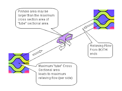


From above limit, maximum relief flow shall be taken as equivalent to the leakage rate through a pinhole of a cross sectional area equal to twice the maximum area of a "tube" cross sectional area. This maximum "tube" cross sectional area may be advised by PHE vendor.

Related Topic

Continue receive FREE stuff & Update.......Subscribe by Email OR RSS
Any comments / advices ?..........Drop it in comment field (below) or send a private email to me...

Wednesday, August 1, 2007

Rule-of-thumb to gage suitability of Plate-Heat-Exchanger in Fluid-Contains-solid or Slurry


Plate Heat Exchanger having narrow channel most probably "not recommended" for fluid contains solid and/or slurry services. However, there are still many success story of using PHE in abovementioned services.

There are some rule-of-thumbs to gage if a plate heat exchanger suitable for fluid contains solid or slurry :

i) 80% of the particles are less than 70% of the interplate gap on the heat exchanger.
ii) 100% of the particles are less than 90% of the interplate gap
iii) Flowing velocity is below erosional velocity (causes premature plate failure)
iv) The minimum wall temperature is above a point where crystal growth is expected.
Further reading


Continue receive FREE stuff & Update.......Subscribe by Email OR RSS
Any comments / advices ?..........Drop it in comment field (below) or sent a private email to me...

Saturday, July 21, 2007

Why not use Fouling factor developed by TEMA for S&T in specifying Plate Heat Exchanger ?


Tubular Exchanger Manufacturers Association (TEMA) has developed a series of fouling factor for Shell and Tube (S&T). These fouling factor are generally higher than Plate Heat Exchanger (PHE), why not use S&T fouling factors to size PHE ?
Isn't this approach conservative and guarantee the performance ?

Reason being...

  • Oversized Plate Heat Exchanger (PHE) required extra CAPEX and extra Space for oversized PHE
  • Tubulence minimise fouling tendencies in correctly sized PHE. Oversized PHE results low actual velocity and increase potential fouling and inefficient heat transfer
  • HTRI studies showed PHE fouling significant lower than Shell & Tube Heat Exchanger (S&T)...factor of 6.7

GUIDELINE : Do not oversized PHE more than 25% against required area.

Further reading :


Continue receive FREE stuff & Update.......Subscribe by Email OR RSS
Any comments / advices ?..........Drop it in comment field (below) or sent a private email to me...

Thursday, June 21, 2007

Plate heat exchanger - Remove some plates...will the pressure drop across the exchanger increase or decrease ?


Plate heat exchanger - Remove some plates...will the pressure drop across the exchanger increase or decrease ?
In a Plate heat exchangers, there are number of plates for the 'hot' fluid and given number of plates for the 'cold' fluid. The cold fluid flows through the cold layers in a parallel type arrangement, same for the hot fluid. The hot fluid layers are typically laid counter-current to the cold layers. By removing plates, you will effectively be reducing the free flow area. This will increase the velocity, which is proportional to the square root of the pressure drop, it is anticipated an increase in pressure drop.


If you benefits from this post...buy me some sweets
Continue receive FREE stuff & Update.......Subscribe by Email OR RSS
Any comments / advices ?..........Drop it in comment field (below) or sent a private email to me...

Monday, June 11, 2007

GRAHAM Plate Heat Exchanger...


Many months ago, i have attended it seminar on vacuum system. Pretty professional in vacuum and heat transfer area...
Graham Corporation, well known supplier for vacuum and heat transfer equipment...
FREE articles available for engineers...
Plate heat exchangers (PHE) consist of a series of thin corrugated plates hung from a carrying bar and clamped between a fixed and movable head plate. The corrugated plates or heat transfer plates are normally stainless steel or other materials ductile enough to allow pressing. Each heat transfer plate is fitted with an elastomeric gasket, partly to seal and partly to distribute the process fluids. Connections in the fixed or movable head plates permit the entry of the process fluids into the plate pack...
Heat Exchangers in Municipal Wastewater Treatment Plants
Spiral heat exchangers have been shown to be economical and reliable for handling municipal wastewater treatment plant sludge heating duties. These exchangers are able to operate reliably when fed with solid and fiber laden fluids, such as sewage sludge. Plate heat exchangers provide an economical option for basic liquid-to-liquid service. Compactness, efficiency, reliability, ease of maintenance, and low initial investment make this exchanger design the choice for many wastewater treatment applications...
Using PC Software to Predict Heat Exchanger Performance
Heat exchanger designers establish operational constraints when they develop a system. In practice, these constraints are conservatively stated, although rarely experienced, during the useful lifetime of a system. Usually, a designer assumes worst-case conditions with respect to the inlet cooling-water temperature and fouling. However, when operational variables change, such as thermal load and cooling-tower temperature, it is necessary to predict exchanger performance under the new conditions so that the impact on all variables in the process loop can be determined...
Continue receive FREE stuff & Update.......Subscribe by Email
Any comments / advices ?..........Drop it in comment field (below) or sent a private email to me...


Sunday, June 10, 2007

ALFA LAVAL - Plate Technology and Designing Plate & Frame Heat Exchanger


Many of us may already familiar with this company...
"
Alfa Laval is the leading manufacturer of plate heat exchangers in the world. We provide you with compact, modern solutions with the highest thermal efficiency."...read more...
Alfa Laval Plate technology
- A detailed look at plate heat exchange (PHE) technology from Alfa Laval

Designing Plate-and-Frame Heat Exchanger - FREE article from ALFA LAVAL...
Continue receive FREE stuff & Update.......Subscribe by Email
Any comments / advices ?..........Drop it in comment field (below) or sent a private email to me...


Saturday, June 9, 2007

Paul Muller - Process Solution Provider...@Heat Exchanger

Paul Mueller Company, a company incepted in 1940, specializes in the design and manufacture of stainless steel processing systems and equipment for the food, dairy, beverage, pharmaceutical, chemical, biotech, and bottled water industries.
In this post, i would like to bring to you it HEAT TRANSFER equipment. MUELLER manufactures :
FREE Sizing program & Articles available in MUELLER :

Accu-Therm Sizing Program
Product Brochures available FREE for download
Ad 375-2
Your Heat Transfer Solutions Provider

Ad 386
Accu-Therm® Plate Heat Exchangers

AT-1601-11
Accu-Therm Plate Heat Exchangers

AT-1607-9
Free-Flow Plate Heat Exchangers

AT-1609-2
Accu-Therm Advantage in Metal Finishing

AT-1610-1
Accu-Therm Back Flush System

AT-1629-3
Accu-Therm Double-Wall Heat Exchangers

AT-1635
Accu-Therm Typical HVAC Cooling Applications

AT-1638-2
Accu-Therm Sanitary Plate Heat Exchangers

AT-1648
New Larger Accu-Therm Plates

BP-1800-1
Brazed Plate Heat Exchangers

O-1453
ASME Plate Heat Exchanger Spec Sheet

O-1454
Non-ASME Plate Heat Exchanger Spec Sheet

TP-103-7
Temp-Plate® Immersion Sections for Metal Finishing Industry

TP-107-2
Temp-Plate Idea Book

TP-108-13
All About Temp-Plate®

TP-111-3
Temp-Plate Energy Banks

TP-406-3
Heat Transfer Solutions

TP-408-3
Double-Embossed Temp-Plate Clamp-On Sections

TP-412-3
Clamp-On Heat Transfer Surface

TP-413-2
Clamp-On Temp-Plate Heat Transfer Surface

TP-433-1
Panel-Coil™
Continue receive FREE stuff & Update.......Subscribe by Email
Any comments / advices ?..........Drop it in comment field (below) or sent a private email to me...