Showing posts with label Material. Show all posts

Saturday, March 27, 2010

Brief About NACE MR 0175

Sulfide -stress cracking is basically a hydrogen-embrittlement phenomenon .Atomic hydrogen enters the steel to cause cracking. The hydrogen is generated on the surface of the steel because of a corrosion reaction. Iron reacts with h2s to form iron sulfide and hydrogen .This hydrogen is generated in atomic form on the steel surface ,where it can either combine to form molecular hydrogen and leave the surface as bubbles or diffuse into steel .This latter process may result in hydrogen embrittlement .Hydrogen sulfide prevents hydrogen recombination & thus promote entry of atomic hydrogen into steel .It is important to note that water must be present for this mechanism to occur ;without it SSC will not be observed ,because the ionization of the hydrogen sulfide is required.

Following is a lecture presentation on NACE Standard MR0175  - Petroleum and Natural Gas Industries – Materials for use in H2S-containing Environments in Oil and Gas Production.
 

Download


Related Post

Saturday, March 20, 2010

NACE MR0103 versus MR0175

NACE MR0103 "Materials Resistant to Sulfide Stress Cracking in Corrosive Petroleum Refining Environments" was developed by Task Group 231 to provide a standard set of requirements for materials used in sour petroleum refinery equipment. In the past, NACE MR01752, "Sulfide Stress Cracking Resistant Metallic Materials for Oilfield Equipment", was frequently referenced for this equipment, even though refinery applications were outside the scope of MR0175. The process used to develop MR0103 is described, followed by a review of the requirements in the standard accompanied by highlights of the differences between MR0103 and the previous and current versions of MR0175.

An Overview of NACE International Standard MR0103 and Comparison with MR0175 


Click here to download the article


A presentation has been prepared by the author which further summary the differences. You may download via the following link : Download Presentation Handout

Thanks to Don BUSH, Jeff BROWN & Keith LEWIS


Related Post

Wednesday, January 14, 2009

Stainless Steel and It Selection Training Module

Display problem ? Click HERE


Stainless steel is one type of material commonly used in oil & gas, refinery, petrochemical, pharmaceutical industries. Stainless steel is a material does not stain and corrosion resistance to many fluids. Stainless steel is rather "soft" and infact it is a cavitation resistance material. This has been discussed in "Stainless Steel SS316 resist to CAVITATION ?".

Recommended :
- Subscribe FREE - Processing Magazine
- Tips on Succession in FREE Subscription

Although Stainless steel is corrosion resistance to many corrosive fluids by formation of protective oxide film, it is still susceptible to pitting corrosion, one of the most destructive forms of corrosion which potentially cause equipment failures on perforation / penetration as discussed in "Pitting Corrosion - Mechanism & Prevention".

Beside pitting corrosion, stainless steel also susceptible to Chloride Stress Corrosion Cracking (CSCC) as discussed in "Chloride Stress Corrosion Cracking & Use correct MOC for seawater service". CSCC is initiation and propagation of cracks in a metal or alloy under tensile stresses and a corrosive environment contains Chloride compounds. Once the crack is initiated, it will propagate rapidly and potentially lead to catastrophic failure. There are more discussion on stainless steel can be found here.

Dr. David Jenkinson, Director of Nickel Institute has produced a series online training modules on "An Introduction to Selection of Stainless Steels for Corrosion Resistance". The online training modules are in audio format which can be read while listen to the explanation. Visual plus audio will quickly assist engineers in understanding the contents.

Click here to begin learning Stainless Steel and It Selection.

Following are complete listing of training module for Stainless Steel and It Selection.

01 - Disclaimer
02 - Module Abstract
03 - Module Information
04 - Chemical Symbols
05 - What Will We Cover?
06 - What Will We Cover? - What is Stainless Steel?
07 - How Stainless Steel Works
08 - Chromium is the Basic Building Block of Stainless Steels
09 - Damage to the Protective Oxide Film
10 - Penetration of the Protective Oxide Film
11 - Corrosion of Embedded Iron in a Stainless Steel Pipe Bend
12 - The protective passive film can be damaged mechanically or chemically in various ways.
13 - What Will We Cover? - Effect of Alloying Additions
14 - Effect of Alloying Additions
15 - 1. Corrosion Resistance
16 - Effect of Alloying Elements on Corrorsion Resistance - Chromium
17 - Effect of Chromium on Atmospheric Corrosion of Steels
18 - Pitting Resistance Equivalent Number (PRE)
19 - Effect of Alloying Elements on Corrosion Resistance - Nickel
20 - Addition of Nickel
21 - Nickel Provides Resistance to Reducing Chemicals
22 - Effect of Alloying Elements on Corrorsion Resistance - Molybdenum
23 - Effect of Alloying Elements on Corrorsion Resistance - Nitrogen
24 - Effect of Alloying Elements on Corrorsion Resistance - Carbon
25 - Hibernia Oil Production Platform
26 - 2. Crystal Structure
27 - Ferritic Stainless Steels
28 - Adding Nickel to Stainless Steels
29 - Austenitic Stainless Steel
30 - Duplex Stainless Steels
31 - List of Ferrite & Austenite Formers
32 - When Choosing a Stainless Steel
33 - What Will We Cover? - Families of Stainless Steels
34 - Families of Stainless Steels
35 - Ferritic Stainless Steels
36 - Typical Compositions of Common Stainless Steels
37 - Type 409 is hte most widely used ferritic stainless steel.
38 - Proprietary Grades
39 - Dishwashers
40 - Stainless Steel Refrigerators
41 - Hot Water Tank
42 - Austenitic Stainless Steels
43 - Typical Compositions of Common Stainless Steels
44 - Domestic Kitchen Sink
45 - Parliament House, Canberra, Australia
46 - Type 304 Stainless Steel Beer Kegs
47 - Chemical Plant
48 - Frederick R. Weisman Art Museum
49 - Wet Electrostatic Precipitator
50 - Duplex Stainless Steels
51 - Typical Compositions of Common Stainless Steels
52 - Type 316LN Stainless Steel - Example
53 - Pressurized Peroxide Reactor
54 - Stainless Steel Meat Racks
55 - Elevator Tower
56 - Families of Stainless Steels
57 - Martensitic Stainless Steels
58 - Typical Compositions of Common Stainless Steels
59 - Stainless Steel Products - Examples
60 - Martensitic Stainless Steel Blades
61 - Precipitation Hardening (PH) Stainless Steels
62 - Typical Compositions of Common Stainless Steels
63 - High Strength S45000 Precipitation Hardening Stainless Steel
64 - What Will We Cover? - Maximizing Corrosion Resistance
65 - Corrosion of Carbon Steel
66 - General Corrosion
67 - Localized Corrosion
68 - Pitting
69 - Once it gets started, pitting is difficult to stop and to repair.
70 - PRE Numbers for Some Ferritic, Austenitic & Duplex Grades
71 - Pitting Corrosion - Effect of Temperature and Chloride Level
72 - Crevice Corrosion
73 - Crevice Corrosion - Example
74 - Chloride Stress Corrosion Cracking (SCC)
75 - Chloride Stress Corrosion Cracking - Example
76 - Copson Curve
77 - Chloride Stress Corrosion Cracking - Effect of Temperature and Chloride Level
78 - What Will We Cover? - High Performance Stainless Steels
79 - High Performance Stainless Steels
80 - Pitting and Crevice Corrosion Resistance
81 - Three Families of High Performance Stainless Steels
82 - PRE Numbers for Some Ferritic, Austenitic & Duplex Grades
83 - Immersed in Seawater Without Cathodic Protection
84 - Heat Exchanger
85 - Flexible Hosing
86 - Heat Exchanger for Aggressive Chloride Service
87 - Zeron 100 Fittings
88 - Condenser Tubes
89 - What Will We Cover? - Nickel Alloys
90 - More Resistant Alloys
91 - Nickel Alloys
92 - Alloy C-276
93 - Summary

Further Reading

Sunday, November 23, 2008

Why Restriction Orifice is some distance from Blowdown valve ? - Clarif #01

Display problem ? Click HERE


A reader MT (abbre.) has read "Why Restriction Orifice is some distance from Blowdown valve ?" and drop me a note. The question are more-or-less as follow :

i) For cases where huge pressure drop is not foreseen or low temperature is not expected downstream of restriction orifice (RO), is it still necessary to provide the minimum distance ?

ii) If the Flare header is Stainless steel (SS), and the process piping is Carbon steel (CS), the Spec break between CS and SS will be shown at the blowdown valve (BDV), i.e. BDV is designed for the most conservative material - SS. In this case, i do not seen the reason of the minimum distance.

Original Intention
The intention of the proposed arrangement in "Why Restriction Orifice is some distance from Blowdown valve ?" is to avoid the BDV stem stuck at position in case the depressured fluid temperature is dropped to sub-zero (below zero degree Celcious).

Responses
i) In case low pressure drop and the depressured temperature is still higher than sub-zero, this requirement is NOT necessary. As long as there is NO risk of fluid temperature drop below zero degree Celcious, then this arrangement is not required.

ii) The process piping upto BDV (excluded BDV) is CS and from BDV onwards is SS. This is a good arrangement with good spec break. The 600mm requirement is mainly related to frozen of moisture content (below zero degree Celcious), it has no/less relationship with the material. Thus, as long as the depressured temperature can drop below zero degree Celcious, regardless what the material of construction (MOC) is, the 600 mm arrangement still applicable.

Related Post

Sunday, November 9, 2008

CO2 Corrosion Using Freecorp Model

Display problem ? Click HERE


In earlier posts "Quick Estimation of CO2 Corrosion Rate" and "CO2 Corrosion Rate Estimation Using M-506 Model", two simple model i.e the DeWaard Milliam model and Norsok M-506 model have been introduced. The DeWaard Milliam model is just a simple chart while the M-506 model has been programmed into a software and available FREE for download.

In this post, another CO2 corrosion rate estimation software FREECORP will be introduced. FREECORP has been released for use by the corrosion research community. It was developed by scientists and programmers at Corrosion Center using publicly available knowledge of oil pipeline corrosion and it is distributed under GPL (General Public License) for FREE use by researchers, practitioners, and students of corrosion phenomena.

"FREECORP V1.0 is a simple corrosion model, strongly rooted in theory, which has been developed exclusively based on public knowledge. Currently, this model is capable of predicting uniform corrosion of carbon steel at a single point in an environment containing carbon dioxide, acetic acid, oxygen, and/or hydrogen sulfide. Iron carbonate film formation, a key factor in carbon dioxide corrosion, is simulated using an empirical correlation to improve the accuracy of corrosion rate prediction. Contributions to corrosion of various corrosion species can be calculated, which enables the exploration of dominant corrosion mechanisms in the corrosion process. Furthermore, polarization curves for each individual electrochemical reaction, net cathodic and anodic reactions and polarization sweeps can be optionally displayed. In a case of hydrogen sulfide corrosion, film formation is calculated and concentration profile of H2S across mass transfer layers on steel surface is displayed."


Related Post

Friday, November 7, 2008

Hot Tapping and Online Valve Change out

Display problem ? Click HERE

Recommended :
Subscribes to FREE Hydrocarbon Processing

Plant debottlenecking and upgrading may involve some hot work and new tie-ins on existing facilities. To facilitate safe construction of new tie-ins, conventionally the existing system will needs to be shutdown and decommission to allow safe hot work. Production loss and inventory loss will incur a large cost for a simple modification. Thus, hot tap technology has been created to facilitate construction of new hot tap while allowing continue production and zero inventory loss. Read more on "Hot Tapping and Line Stopping Without Shutdown Services". You may view the the detailed hot tapping procedure by click this link.

In normal operation of a plant, certain unavoidable phenomena such as equipment wear and tear, corrosion, decay, etc would lead to valve deteriorate and required to be replaced / changed out. Similarly, this activities would lead production shutdown and inventory loss in order to carry out the change-out activities. Now a new technique has been introduced to remove and replace a ball valve without shutting down the plant. It has been successfully implemented in changed-out of a 6" ball valve located on a live cryogenic tank. This surely and significantly reduction in production and inventory losses. In principle, it apply the similar hot tapping procedure to carry out the valve change-out. Read more on "Ground-breaking procedure on live propane tank avoids costly shutdown".

Applying hot tapping and valve change-out with live plant, it is a significant challenge to all parties involve. Several factors shall be in consideration :

i) Safety Analysis - The entire hot tapping work shall be properly analysed. All stringent safety analysis i.e PHA, HAZOP, etc shall be properly conducted and documented.

ii) Competent operator - The entire works shall be carried out by a team of competent operator. In some counties, the group of people shall have license to carry such activities.

iii) Cost - The hot tap activities is highly hazard and require high technology to conduct this activities. This will results a high cost.

Although hot tapping and online valve change-out is very attractive, nevertheless, there are still many established oil and gas operator keep them away from using this technology. The main concern still the risk involve and confident and success stories for these techniques. Having said that, it no doubt is a technique may be considered in special case.

What do you think ?

Related Post

Sunday, October 26, 2008

Common FAQs Related to NACE Standard MR0175 / ISO 15156

Display problem ? Click HERE

Recommended :
Subscribe FREE - Metal Finishing

NACE Standard MR0175 / ISO 15156 - Petroleum and Natural Gas Industries – Materials for use in H2S-containing Environments in Oil and Gas Production
was established to provides limits of H2S partial pressure for precautions against sulfide stress cracking (SSC) and guidance for the selection and specification of SSC-resistant materials.

Following are some commonly asked question related to this standard.

  1. Why NACE MR0175 Called NACE MR0175/ISO 15156 ?
  2. What is latest error in NACE MR0175 / ISO 15156
  3. How to use of MR0175 / ISO15156
  4. How NACE Standards Applied in Farris Pressure Relief Valves ?
  5. How NACE MR0175-2003 Impact on API 6A Equipemnt and Customer ?
  6. How ISO 15156 maintenance activities Functions works ?
  7. How do I know which are the latest editions of the three parts of NACE MR0175/ISO 15156 ?
  8. Are NACE MR0175/ISO 15156 and ISO 15156 identical in their technical content ?
  9. Are you aware that the page numbering of NACE and ISO editions of the standard sometimes differ ?
  10. How do these documents relate to previous editions of NACE MR0175 ?
  11. How often will the parts of NACE MR0175/ISO 15156 be updated ?
  12. What happens when amendments are required in the intervening period ?
  13. What status does a Technical Corrigendum or a Technical Circular have ?
  14. Are Technical Corrigenda and Technical Circulars incorporated into a standard when it is revised ?
  15. What is the difference between a Technical Corrigendum and a Technical Circular ?
  16. Where can Technical Corrigenda and Technical Circulars be obtained ?
  17. Does the ISO 15156 Maintenance Panel provide a consultancy service concerning materials and their application in sour service ?
  18. Can the ISO 15156 Maintenance Panel provide advice on the use of alternative materials not listed in the standard ?
  19. Will the ISO 15156 maintenance Panel provide interpretations for earlier editions of NACE MR0175 ?
  20. How do I get my material certified to NACE ?
  21. Is it all right for my company to require compliance with the 2002 version of MR0175 ?
  22. What do we need to put on the certificate?
  23. Can you give me the name of someone on a particular committee that I can call to ask a question about a standard ?
  24. I need to speak with someone who can give me advice on my water treatment system, tell me the best way to apply cathodic protection to my pipeline, or answer another technical question.
  25. I have a certain opinion on cathodic protection, and my customer has a different opinion. What is NACE’s position on this ?
If you aware of any links in relation to NACE Standard MR0175 / ISO 15156, please drop me note. Let accumulate the resource together.

Related Post

Saturday, October 25, 2008

Material Selection... USER Responsibility

Display problem ? Click HERE

Recommended :
Subscribe FREE - Metal Finishing

This is a brief history about how NACE MR0175 / ISO 15156 is established since 1950s. It begun after World War II with the establishment of Technical report 1A152 "Sour Oil Well Corrosion" and 1B159 "Well Completion & Corrosion Control of High Pressure Gas Wells" when the demand to gas increased. This followed by NACE 1B163 "Recommendations on Material for Sour Service" and NACE 1F166 "Sulfide Cracking-Resistance Metallic Material for Valves for Production and Pipeline Service" in 1960s. First published of MR 0175 in 1975 and TM0177 "Testing of Metals for Resistance to Sulfide Stress Cracking at Ambient Temperatures" in 1978 and followed by TM0284 "Evaluation of Pipeline Steels for Resistance to Stepwise Cracking" in 1990. MR0175 is then merged with some EFC reports i.e. EFC#16 & #17 and finally first published the NACE MR0175 / ISO 15156 in 2003/2004.

Critical Improvements
Several critical improvements in the NACE MR 0175 with the published of NACE MR0175 / ISO 15156 in 2003/2004 :
  • Inclusion of Stepwise cracking (SWC), Stress Oriented Hydrogen-Induced Cracking (SOHIC), Soft-zone cracking (SZC), etc. Read more on these corrosion type in "What are the concerns related to H2S ?"
  • USER who are specifying and/or operating the equipment has full responsibility to ensure a material is works satisfactory in the intended environment. USER is responsible for the material selection. On the other hand, MANUFACTURER is responsible for meeting the metallurgical requirements.
  • For revamping/modification of existing facilities and the material was designed for previous revision of NACE MR0175, if USER has the opinion the fluid condition stayed as before, USER may keep the existing material.
  • NACE MR0175 / ISO 15156 is solely a guide documents for a proper selection of material in H2S environment. This documents providing list of material resistant to H2S environment, however, the material is not immune to to H2S environment. It implies that improper design, selection, fabrication, etc. may still lead to these material susceptible to H2S environment.
USER Responsibility
From above statements, the use and implementation of NACE MR0175 / ISO 15156 in H2S environment is within the decision of USER. A metallurgist and material engineer with the assistance of process and chemical engineer within the USER group i.e. COMPANY, CONTRACTOR, and LICENSOR are playing a major role in defining and implementing this standard. DO NOT RELY ON MANUFACTURER & VENDOR !!!

Read more in "Changes to NACE Standard MR0175-2003"
Download

Related Post

Sunday, June 29, 2008

Material for High H2SO4 Concentration and High Temperature & Pressure

Display problem ? Click HERE

Recommended :
Subscribe FREE - Plant Services

In earlier post "FAYF - Acid Solution Storage", Carbon Steel (CS) may be used for concentrated Sulfuric acid (H2SO4) at ambient temperature. However, diluted H2SO4 may severely corrodes CS. Non-metal material (PVC, PFA, FEP, PTFE) may be used for concentrated and diluted H2SO4 solution. Nevertheless, these materials lose it strength at high temperature and high pressure operation. Using non-metal material may not be cost effective at high temperature and high pressure design.

Thus for high temperature and high pressure operation, exotic material Zirconium and its alloy may be considered.

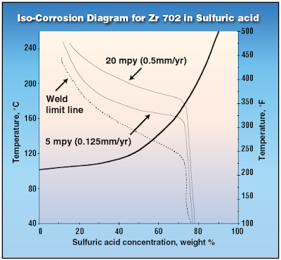
Zirconium has excellent corrosion resistance in all concentrations of sulfuric acid up to 70% and well above boiling.


Zirconium Limitation and its work-around...
H2SO4 concentration exceeded 55%, there will be preferential corrosion attack at weld. WIth H2SO4 concentration exceeded 65%, there may be Sulfide Stress Corrosion Cracking (SSCC) in Zirconium. Thus, stress-relief anneal (heat treatment) should be conducted to avoid above mentioned preferential corrosion and SSCC. However, In the presence of fluoride ions, Zirconium should not be used with sulfuric acid.

For H2SO4 concentration exceeded 70%, other material such as Tantalum may be considered. Tantalum can take any H2SO4 concentration with temperature upto 200 degC.

Read more details explanation in


Note :
*This article is only available FREE to Chemical Engineering Magazine registered user.
Login required.
Registration FREE (Click HERE).
** Download immediately as article available FREE within short period (JUNE 2008 only)
*** Found lost link or unable to download, may contact me...

RELATED POST

Wednesday, June 18, 2008

What are the concerns related to H2S ?

Display problem ? Click HERE


High demand in energy source i.e. petroleum, LNG, etc leads to high pricing of these sources. This has given addition incentive to explore those sour field. Sour field being Oil or gas contains high H2S which potentially lead to material cracking.

What are the problem or concerns related to H2S ?

Toxic
First and far most important concern related to H2S is high toxicity. Human exposure of H2S at high concentration within a short period could lead to fatal.

Environment
H2S release to atmosphere would mix and dissolve in moisture and form acid rain which is corrosive and create human health concerns.


Corrosion & Stress Cracking
i) Sulphide Stress Corrosion Cracking (SSCC)
H2S dissolved in water to form weak acid promote corrosion and form free hydrogen. Free Hydrogen will penetrate the metal, reduce ductility of metal and potentially lead to stress failure below it yield stress, results Sulphide Stress Corrosion Cracking (SSCC).

Sulfide stress corrosion cracking (SSCC) is cracking of metal involving corrosion and tensile stress (residual and/or applied) in the presence of water and H2S. SSC is a form of hydrogen stress cracking (HSC) and involves embrittlement of the metal by atomic hydrogen that is produced by acid corrosion on the metal surface. Hydrogen uptake is promoted in the presence of sulfides. The atomic hydrogen can diffuse into the metal, reduce ductility and increase susceptibility to cracking. High strength metallic materials and hard weld zones are prone to SSC. (Source : NACE MR 0175)

Apart from SSCC, H2S also cause other cracking, including stress corrosion cracking (SCC), hydrogen-induced cracking (HIC) and stepwise cracking (SWC), stress-oriented hydrogen induced cracking (SOHIC), soft zone cracking (SZC) and galvanically induced hydrogen stress cracking.

Hydrogen Stress Cracking (HSC)
HSC refer to cracking that results from the presence of hydrogen in a metal and tensile stress (residual and/or applied). HSC describes cracking in metals that are not sensitive to SSC but which may be embrittled by hydrogen when galvanically coupled, as the cathode, to another metal that is corroding actively as an anode. The term galvanically induced HSC has been used for this mechanism of cracking.*

Stress Corrosion Cracking (SCC)
SCC refer to cracking of metal involving anodic processes of localized corrosion and tensile stress (residual and/or applied) in the presence of water and H2S. Chlorides and/or oxidants and elevated temperature can increase the susceptibility of metals to this mechanism of attacks. *

For Chlorides stress corrosion cracking (CSCC), read more in Chloride Stress Corrosion Cracking & Use correct MOC for seawater service

Hydrogen-Induced Cracking (HIC)
HIC refer to planar cracking that occurs in carbon and low alloy steels when atomic hydrogen diffuses into the steel and then combines to form molecular hydrogen at trap sites. Cracking results from the pressurization of trap sites by hydrogen. No externally applied stress is needed for the formation of hydrogen-induced cracks. Trap sites capable of causing HIC are commonly found in steels with high impurity levels that have a high density of planar inclusions and/or regions of anomalous microstructure (e.g. banding) produced by segregation of impurity and alloying elements in the steel. This form of hydrogen-induced cracking is not related to welding.*

Stepwise Cracking (SWC)
SWC refer to cracking that connects hydrogen-induced cracks on adjacent planes in a steel. This term describes the crack appearance. The linking of hydrogen-induced cracks to produce stepwise cracking is dependent upon local strain between the cracks and embrittlement of the surrounding steel by dissolved hydrogen. HIC/SWC is usually associated with low-strength plate steels used in the production of pipes and vessels.*

Stress-Oriented Hydrogen-Induced Cracking (SOHIC)
SOHIC refer to staggered small cracks formed approximately perpendicular to the principal stress (residual or applied) resulting in a “ladderlike” crack array linking (sometimes small) pre-existing HIC cracks. The mode of cracking can be categorized as SSC caused by a combination of external stress and the local strain around hydrogen-induced cracks. SOHIC is related to SSC and HIC/SWC. It has been observed in parent material of longitudinally welded pipe and in the heat-affected zone (HAZ) of welds in pressure vessels. SOHIC is a relatively uncommon phenomenon usually associated with low-strength ferritic pipe and pressure vessel steels.*

Soft Zone Cracking (SZC)
SZC refer to form of SSC that may occur when a steel contains a local “soft zone” of low yield strength material. Under service loads, soft zones may yield and accumulate plastic strain locally, increasing the SSC susceptibility to cracking of an otherwise SSC-resistant material. Such soft zones are typically associated with welds in carbon steels.*

* Source : NACE MR 0175 - ISO 15156

Related Post

Tuesday, June 3, 2008

Stainless Steel SS316 resist to CAVITATION ?

Display problem ? Click HERE


Stainless Steel (i.e. SS316) is "soft" compare to other material e.g Cast Iron, Duplex stainless steel, etc. due to it has high ductility. However, high ductility of stainless steel make a good material resist cavitation.

How stainless steel against cavitation ?

The main reason is due to work-hardening property of Stainless Steel. Hammering a SS316 strip would lead to surface work-hardens and difficult to change the shape.

Similar phenomenon occurs when microjet impacting on the surface of stainless steel and caused the Stainless steel work-hardens, and increase resistance to further cavitation.

SS316 resists cavitation about 10-15 times better than cast iron whilst CA6NM (modified SS316) is roughly 2-3 times more resistant to cavitation as compared to SS 316.

Related Topic

Sunday, June 1, 2008

FAYF - Acid Solution Storage

Display problem ? Click HERE


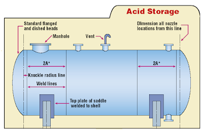
Chemical Engineering share a new FAYF in May 2008. This FAYF is related to some tips and requirements of Acid Solution Storage especially in Material of Construction (MOC).

The acid solution discussed in this FAYF includes :
  • Sulfuric acid (H2SO4)
  • Phosphoric acid (H3PO4)
  • Hydrochloric acid (HCl)
  • Nitric acid (HNO3)
  • Hydrofluoric acid (HF)
Some simple tips in this FAYF as follow :

Sulfuric acid (H2SO4)
  • Reaction in H2SO4 potentially generate hydrogen (H2), ensure proper venting and dispersion
  • Carbon steel (CS) good for concentrated H2SO4 at normal ambient temperature.
  • Diluted H2SO4 is severely corrodes CS. Shall keep away moisture from CS tank e.g. Nitrogen blanketting
  • Polyvinyl chloride (PVC) pipe may be used
Phosphoric acid (H3PO4)
  • Rolled upward 3 m from tank bottom to allows free weld expansion and contraction (reduced stress)
  • Avoid corner weld which normally undue stresses occur (corrosion)
  • Heating required to avoid freezing in storage.
  • Use SS316 or rubber lined CS or Fiberglass Reinforced plastic. Avoid CS.
Hydrochloric acid (HCl)
  • HCl (fume) vent send to scrubber or flare for proper disposal
  • Use Rubber lined CS or Glass lined CS or FRP.
Nitric acid (HNO3)
  • Similar to HCl, Nitrogen Oxides (NOx) vent to scrubber
  • Upto 95 wt% @ ambient, use SS 304L
  • More than 95 wt%, use Aluminium Alloy
Hydrofluoric acid (HF)
  • Anhydrous HF has high vapor pressure. Tank should design for 60 psig (as minimum)
  • All welds shall be X-rayed and Stress-Relieved.
  • HF fume shall be vented to scrubber or flare
  • May use CS upto 66 degC and 70wt% HF
  • Potential Hydrogen Blistering (Read more how H2 blistering form ?). Periodic tank inspection for blistering.


Note :
*Login required.
Registration FREE.
** Download immediately as article available FREE within short period.
*** Found lost link or unable to download, may contact me...


References
1. Grossel, S., Safe Efficient Handling of Acids, Chem. Eng. December 1998, pp. 104–112.
2. Anon., Phosphoric Acid, Rhone-Poulene Basic Chemicals Co., Shelton, Conn. (1992).


RELATED POST

Friday, January 18, 2008

Nano Technology - Revolution in Material Selection

Display problem ? Click HERE

Nano technology is getting important nowadays. Special characteristic of nano material such as high thermal conductivity, high electrical conductivity, high strength, etc would definitely will bring a great revolution in material selection and change the way we doing things.

There is a great detail introduction and substantial links to other websites related to nano-technology in here.

Let see simple presentation by Dr. Julie MacPHERSON, a researcher intended to find the way to produce nano-carbon in most affordable cost.


Related Post
Continue receive FREE stuff & Update.......Subscribe by Email OR RSS
Any comments / advices ?..........Drop it in comment field (below) or send a private email to me...

Monday, December 10, 2007

Minimum Four Factors For Selection of Head Type on a Vessel


There are many head types attached to a vessel, column or drum such as hemispherical, semi-hemispherical, elliptical, flanged, etc. All these have been used in many application and however the selection of the head type is normally not documented in any process nor mechanical document and drawings. The question of application of head type has been raised many time by young engineers and the answer has been repeated many times. There is some incentive behind to list out some common reasons in application of head type.

There are few factors affecting the selection of head type :
  • Allowable stress & Material used
  • Access internals
  • Constructibility / fabrication limitation
  • Cost Saving
Allowable Stress & Material used
From stress and material saving perspective, for a vessel exposing to very high pressure hemispherical head is having highest allowable stress and minimum material. This will be followed by elliptical head and last flanged head (least allowable stress). Generally an elliptical head is in used.

Access Internals
In large vessel with the needs of accessing internals, normally an access hole (normally used manhole) will be provided.

Access_internal

However, in small vessel with internals, a flanged head is preferred. Most of the time a swing davit will be installed on the flanged head to held the flange without assistance of any hoist.

Constructibility / fabrication limitation
Flanged head some time is used due to complexity of fabrication. There are many event where a inline condenser is mounted on top of a column.

condenser_top_mounted

In some event where the column is small diameter (i.e. 1000mm) and a condenser with 800m ND needs to be mounted on top, there will be difficulties to use a elliptical head. those a flanged head with mating concentric reducer will be used. Apart it serve as manhole to access the internals such as demister.

Cost Saving
Sometime process and operation may required a manhole (for any specific reason) on a small vessel. Apart from construction limitation, providing a flanged head will solve the constructibility problem, it also act as manhole. Some cost saving is expected.

MW

Above are some common reasons for selection of head type. I am sure there are others special reason(s) for the selection in Petrochemical & Chemical industry. If you have any example, why not sure with us ? OR if you have any photos for above applications, why not sent to me so that i can upload here ?

Related Topics


Continue receive FREE stuff & Update.......Subscribe by Email OR RSS
Any comments / advices ?..........Drop it in comment field (below) or sent a private email to me...

Thursday, September 20, 2007

Design fault in Hydrogen Attack of Residue Hydrodesulfurrization


In earlier post,<< High Temperature Hydrogen Attack in metal & alloy>> there are some discussion on how hydrogen attack in metal & alloy is initiated and a paper in recent activities in hydrogen attack.

How many of you have ever heard accident caused by High Temperature Hydrogen Attack in metal & alloy ? How severe is this attack ?

By chance, i found an accident of High Temperature Hydrogen attack on Carbon Steel piping at the outlet of a Pressure Relief Valve. This accident happened in the Residue Hydrodesulfurization unit in Japan. This accident has killed five (5) operators and injured three (3) operators.


High temperature gas contain Hydrogen is compressed and fed to furnace and reactor. Heating and reaction taken place in the furnace and reactor and hot product is fed to a separator. Pressure Relief Valve protecting compressor is bypassed the furnace and reactor and connected to downstream of furnace and reactor. Generally the is no flow passing the Pressure Relief Valve discharge and is expected the discharge piping is always under low temperature. Those High temperature hydrogen attack is not expected in the Pressure Relief Valve discharge piping and design has not considered it.

After the incident, investigation has reported that the burst piping is caused by High Temperature Hydrogen Attack. How the piping is exposed high temperature and how the hydrogen can get into this piping ?

If you review details drawing in figure 4 in the report, you will find that the piping burst at the location closed to the main pipe. During normal operation, hot gas is flowing through the main pipe and main pipe is heated to high temperature. Hot main pipe will transmit heat to the branch from Pressure relief Valve with conduction effect. Temperature is gradual reduced with distance from the branch tie-in.

In the event compressor is overpressure, pressure relief valve popped will release high temperature gas with hydrogen rich in it. Whenever it passing through the pipe, hot piping metal will pick-up the hydrogen, react with Carbon in the piping and form Methane and this will weaken the hot carbon steel piping.

One note has not been addressed is that there is residue hydrogen gas in the product line. This continuously expose the branch with hydrogen. Hydrogen pick-up activity is continues during normal operation.

Lesson here is never under-estimated Hydrogen attack in metal and alloy. Whenever dealing with hydrogen, special attention shall be taken for those non- continuous operating lines.

Related reading


Continue receive FREE stuff & Update.......Subscribe by Email OR RSS
Any comments / advices ?..........Drop it in comment field (below) or sent a private email to me...

Friday, September 14, 2007

High Temperature Hydrogen Attack in metal & alloy


High Temperature Hydrogen Attack (HTHA) is a form of degradation caused by hydrogen reacting with carbon to form methane in a high temperature environment.

C + 4H --> CH4

The methane forms and stays in grain boundaries and voids however it does not diffuse out of the metal. Once it accumulated in the grains and voids, it expands and forms blister , weaken the metal strength and initiate cracks in the steel.

High-strength low-alloy steels are particularly susceptible to this mechanism, which leads to embrittlement of the bulk parent metal (typical C-0.5 Mo steels). The embrittlement in the material can result in a catastrophic brittle fracture of the asset.

Following is a picture of Blistering in metal due to High Temperature Hydrogen Attack.


This paper summarizes the research and investigation activities related to HTHA, including the general information about HTHA.


"Exisitng C-0.5Mo steel in hydrogen service is still our concern in industries. High Temperature Hydrogen Attack (HTHA) has been one of the major problems in petroleum and petrochemical industry because of its effect. Since the original Nelson Curves was suggested in 1949 to define the operating limits for steels used in hydrogen service to avoid HTHA, a number of research and investigation activities on HTHA have been carried out mainly in The United States and Japan.

In USA, API summarized these data as Publication 941 – “Steels for Hydrogen Service at Elevated Temperatures and Pressures in Petroleum Refineries and Petrochemical Plants” in 1970 and, since then, it has been widely used for material selection in hydrogen service, operation and maintenance in petroleum and petrochemical plants. In Japan, some organizations such as JSM, JPVRC and PVT have been tackling HTHA problems since 1970’s, and they suggested some assessment procedures for HTHA. Importance is how to evaluate this equipment to keep plant integrity.
"

Related reading


Continue receive FREE stuff & Update.......Subscribe by Email OR RSS
Any comments / advices ?..........Drop it in comment field (below) or sent a private email to me...