Showing posts with label Fire. Show all posts

Sunday, December 27, 2009

Calculate Wetted Surface Area For VERTICAL Cylindrical vessel with Elliptical Head

Recommended :
Tips on Succession in FREE Subscription
Subscribes to FREE Hydrocarbon Processing

This post is in response to some readers request for calculation of Wetted Surface Area For VERTICAL Cylindrical vessel with Elliptical Head.


Earlier post "Calculate Wetted Surface Area For Horizontal Vessel With Elliptical Head" has presented an accurate equation may be used to calculate wetted surface area for Horizontal Cylindrical Vessel with Elliptical Head. Simplified equations also presented in "Calculate Wetted Surface Area For Horizontal Vessel With Elliptical Head (Simplified)"
to calculate the wetted surface area.
 

This principle in deriving Wetted Surface Area For VERTICAL Cylindrical vessel with Elliptical Head was based on the accurate equations as presented in "Calculate Wetted Surface Area For Horizontal Vessel With Elliptical Head". Two main principles used were :
  • horizontal vessel liquid height (H) reached maximum level (d) where H = d
  • horizontal vessel tan-tan length (L) equal to the vessel vessel liquid height ( l) where L = l
Wetted Surface Area (Cylindrical section)
Wetted Surface Area for Cylindrical section can be calculated with following equation :


Wetted Surface Area (Elliptical head)
Wetted Surface Area for Elliptical head (one head) can be calculated with following equation :


where
d = Vessel inside diameter (m)
l = Liquid height from bottom tangent line (m)

Example
An ellipsoidal heads VERTICAL vessel with internal diameter (d) of 1m and liquid level height from bottom tangent line is 2m. Determine wetted surface area. 
 
d = 1m
l = 2m
Awet,Cyl = PI x d x l = PI x 1 x 2 = 6.28 m2
Awet,Head = 1.084 x d^2 = 1.084 x 1^2 = 1.084 m2
Total wetted surface area, Awet,total = Awet,Cyl + Awet,Head = 7.37 m2

Ref : "Accurate Wetted Areas for Partially Filled Vessels", by Richard C. Doane, "Chemical Engineering", December 2007
Download

*If you have any useful program and would like to share within our community, please send to me.

Related Post

Saturday, October 10, 2009

Interesting Relationship Between Carbon number and LFL & UFL

Display problem ? Click HERE

Recommended :
Subscribes to FREE Hydrocarbon Processing

A mixture is combustible / flammable if and only if the hydrocarbon composition is within mixture LFL/LEL and UFL/UEL as discussed in "Estimate Mixture Flammability & Explosivity At Reference P & T. As the operating pressure (P) and temperature (T) change (from reference P & T, the mixture LFL/LEL and UFL/UEL at P & T will change accordingly. In recent works, found in literature an interesting relationship between number of Carbon (in paraffin hydrocarbon) with LFL/LEL and UFL/UEL. This relationship is pretty useful especially when you have no information on hand.

A paraffin hydrocarbon with NC of Carbon (C), the Upper Explosive Limit (UFL) and Lower Explosive Limit (LFL) can be established with following equations :


Example
A Methane (CH4) contains One (1) Carbon. From literature, the UFL = 15 vol% and LFL = 5%.
From above equations,

UFL = 1 / (0.01337 x 1 + 0.05151)
UFL = 5.6% (compare to 5%)

LFL = 1 / (0.1347 x 1 + 0.04343)
LFL = 15.4% (compare to 15%)

A Propane (C3H8) contains Three (3) Carbon. From literature, the UFL = 10.1 vol% and LFL = 2.1%. From above equations,

UFL = 1 / (0.01337 x 3 + 0.05151)
UFL = 10.9% (compare to 10.1%)

LFL = 1 / (0.1347 x 3 + 0.04343)
LFL = 2.2% (compare to 2.1%)

A Hexane (C6H14) contains Six (6) Carbon. From literature, the UFL = 7.0 vol% and LFL = 1.25%. From above equations,

UFL = 1 / (0.01337 x 6 + 0.05151)
UFL = 7.6% (compare to 7%)

LFL = 1 / (0.1347 x 6 + 0.04343)
LFL = 1.2% (compare to 1.25%)

Above equation is just equations for quick estimation. It may provide some idea of UFL and LFL when no information is available. The error could be large for certain component i.e. Octane. For design and practical use, an in depth method shall be employed.


Related Topic

Saturday, September 5, 2009

Relate LFL to MOC

Display problem ? Click HERE


Recommended :
Subscribes to FREE Hydrocarbon Processing

Minimum oxygen concentration (MOC) is minimum quantity of oxygen required present in hydrocarbon mixture so that a fire can be initiated and propagated. Below this limit, a fire will not form. More discussion in "Minimum Oxygen Concentration (MOC) for Flare Purge". A mixture is combustible / flammable if and only if the hydrocarbon composition is within mixture LFL/LEL and UFL/UEL as discussed in "Estimate Mixture Flammability & Explosivity At Reference P & T One shall remember, as the operating pressure (P) and temperature (T) change (from reference P & T, the mixture LFL/LEL and UFL/UEL at P & T will change accordingly. This post will discuss the relationship between MOC with LFL/LEL.

LFL Relate to MOC
LFL is minimum hydrocarbon (HC) concentration in air which a mixture will burn when an ignition source is present. LFL can be written as follow


MOC is minimum oxygen present in hydrcarbon mixture which a mixture will burn. MOC can be written as follow


Combining [1] & [2],


Combustion of Hydrocarbon


Above equation may be used to estimate MOC if you know the LFL of hydrocarbon.

Example
1) A Ethane (C2) having LFL of 3.0 vol% (Refer to "Estimate Mixture Flammability & Explosivity At Reference P & T". Estimate MOC of Ethane.

Combustion of C2H6,

C2H6 + d.O2 ==> 2CO2 + 3H2O

a = 2
b = 6
c = 0
d = 2 + 6 /4 - 0/2 = 3.5

MOC = 3.5 x 3.0 = 10.5 Vol%, close to 11.2 vol% in literature.


2) A n-butane (nC4) having LFL of 1.86 vol% (Refer to "Estimate Mixture Flammability & Explosivity At Reference P & T". Estimate MOC of n-butane.

Combustion of C4H10,

C4H10 + d.O2 ==> 4CO2 + 5H2O

a = 4
b = 10
c = 0
d = 4 + 10 /4 - 0/2 = 6.5

MOC = 6.5 x 1.86 = 12.1 Vol%. Close to 12.3 vol% in literature.

Related Topic

Wednesday, September 2, 2009

Estimate Mixture Flammability & Explosivity At Operating P & T

Display problem ? Click HERE

Recommended :
- Subscribe FREE - Chemical Processing
- Tips on Succession in FREE Subscription


Earlier post "Estimate Mixture Flammability & Explosivity At Reference P & T" discussed about the Lower flammable limit (LFL) or Lower Explosive Limit (LEL) and Upper flammable limit (UFL) or Upper Explosive Limit (UEL) for single component fluid and mixture at reference pressure (Pref) and temperature (Tref). This post will discuss the way to correlate the LFL/LEL and UFL/UEL at Pref and Tref and operating pressure (P) and temperature (T) .

Temperature & Pressure Corrected LFL/LEL & UFL/UEL
Below are two equations may be used to correlate the LFL/LEL and UFL/UEL at Pref and Tref and operating pressure (P) and temperature (T).


One shall take note that these equations are used for single component. For a mixtures, the LFL/LEL and UFL/UEL at operating pressure (P) and temperature (T) will be calculated using following equation (as discussed in "Estimate Mixture Flammability & Explosivity At Reference P & T":


Align Center

Calculation Steps
2 steps in determining mixtures LFL/LEL and UFL/UEL at operating pressure (P) and temperature (T) .
(i) Estimate LFL/LEL and UFL/UEL at operating pressure (P) and temperature (T) for every component in a mixture
(ii) Estimate mixture LFL/LEL and UFL/UEL

Example
A mixture contains of Methane, Ethane and Propane with volume% of 20%, 20% and 60%. Estimate UEL at (i) 20 degC & 101.325 Pa, (ii) 70 degC & 3 MPa.

Data
Methane (C1)
UELC1,20C,1ATM = 15.0%, EC1,combustion = 212.79 kcal/mole

Ethane (C2)
UELC2,20C,1ATM = 12.4%, EC2,combustion = 372.81 kcal/mole

Propane (C3)
UELC3,20C,1ATM = 10.1%, EC3,combustion = 526.74 kcal/mole

Output
(i) UELMix at 20 degC & 101.325 Pa
UELMix = 1 / [ 0.2/15 + 0.2 /12.4 + 0.6 / 10.1 ]
UELMix = 11.25 vol% at 20 degC & 101.325 kPaA

(ii) UELMix at 70 degC & 3 MPa
UELC1,7oC,3MPa
= 15 x [1+0.75(70-20)/212.79]
+ 20.6 x [Log10(3)+1]
= 48.07 vol%

UELC2,7oC,3MPa
= 12.4 x [1+0.75(70-20)/372.81]
+ 20.6 x [Log10(3)+1]
= 44.08 vol%

UELC3,7oC, 3MPa
= 10.1 x [1+0.75(70-20)/526.74]
+ 20.6 x [Log10(3)+1]
= 41.25 vol%

UELMix,70C,3MPa = 1 / [ 0.2/48.07 + 0.2 /44.08 + 0.6 / 41.25 ]
UELMix,70C,3MPa = 43.02 vol% at 70 degC & 3 MPaA

Related Topic

Monday, August 31, 2009

Estimate Mixture Flammability & Explosivity At Reference P & T

Display problem ? Click HERE

Recommended :
- Subscribe FREE - Chemical Engineering
- Tips on Succession in FREE Subscription

Lower flammable limit (LFL) or Lower Explosive Limit (LEL) is minimum vapor concentration in air which a mixture will burn when an ignition source is present. Upper flammable limit (UFL) or Upper Explosive Limit (UEL) is maximum vapor concentration in air which a mixture will burn when an ignition source is present. Concentration of mixture of vapor in air below LFL/LEL (too lean) or above UFL/UEL (too rich), mixture will not burn even an ignition source is present. Therefore, flammable range or explosive range is concentrations between LFL/UFL and UFL/UEL.

Component LEL & UEL
LFL/LEL and UFL/UEL for some common gases are indicated in table below. Some of the gases are commonly used as fuel in combustion processes.

Fuel Gas (LFL/LEL)
(%)
(UEL/UFL)
(%)
Acetaldehyde 4 60
Acetone 2.6 12.8
Acetylene 2.5 81
Ammonia 15 28
Arsine 5.1 78
Benzene 1.35 6.65
n-Butane 1.86 8.41
iso-Butane 1.80 8.44
iso-Butene 1.8 9.0
Butylene 1.98 9.65
Carbon Disulfide 1.3 50
Carbon Monoxide 12 75
Cyclohexane 1.3 8
Cyclopropane 2.4 10.4
Dimethyl Ether3.4
27
Diethyl Ether 1.9 36
Ethane 3 12.4
Ethylene 2.75 28.6
Ethylene Oxide
3.6
100
Ethyl Alcohol 3.3 19
Ethyl Chloride 3.8 15.4
Fuel Oil No.1 0.7 5
Hydrogen 4 75
Isobutane 1.8 9.6
Isopropyl Alcohol 2 12
Gasoline 1.4 7.6
Kerosine 0.7 5
Methane 5 15
Methyl Alcohol 6.7 36
Methyl Chloride 10.7 17.4
Methyl Ethyl Ketone 1.8 10
Naphthalene 0.9 5.9
n-Heptane 1.0 6.0
n-Hexane 1.25 7.0
n-Pentene 1.65 7.7
Neopentane 1.38 7.22
Neohexane 1.19 7.58
n-Octane 0.95 3.20
iso-Octane 0.79 5.94
n-Pentane 1.4 7.8
iso-Pentane 1.32 9.16
Propane 2.1 10.1
Propylene 2.0 11.1
Silane 1.5 98
Styrene 1.1 6.1
Toluene 1.27 6.75
Triptane 1.08 6.69
p-Xylene 1.0 6.0

Note : The limits indicated are for component and air at 20oC and atmospheric pressure.

Mixture LFL/LEL & UFL/UEL
A mixture is combustible / flammable within mixture LFL/LEL and UFL/UEL. Common units for both limits is mole (or volume) percent fuel in air [moles fuel/(moles fuel + moles air)]. A mixture LFL/LEL and UFL/UEL limits can be calculated using the equations first proposed by Le Chatelier in 1891 :


Example
A vapor contains of 20 vol% of Methane (C1), 20 vol% of Ethane (C2) and 60 vol% of Propane (C3). Find LEL of this mixture at 20 degC and Atmospheric pressure (101325 kPaA).

LEL
C1 = 5 vol% at 20 degC & 101.325 kPaA
LELC2 = 3 vol% at 20 degC & 101.325 kPaA
LELC3 = 2.1 vol% at 20 degC & 101.325 kPaA

LELMix = 1 / [ 0.2/5 + 0.2 / 3 + 0.6 / 2.1 ]
LELMix = 2.55 vol% at 20 degC & 101.325 kPaA

Above LEL may be linked to MOC as discussed in "Minimum Oxygen Concentration (MOC) for Flare Purge". Vapor mixture flammability & explosivity at Operating P & T discussed in this post.

Related Topic

Saturday, August 29, 2009

Minimum Oxygen Concentration (MOC) for Flare Purge

Display problem ? Click HERE

A fire is formed or a flame can sustains and propagate, three main elements shall present as defined in well known FIRE triangle. There are combustible material (or fuel), oxygen (O2) and heat. See following image. One additional characteristic shall also present is the potential of chain reaction to maintain continuous combustion before any of these three elements is removed. This speed of chain reactions define if a mixture is combustible (slow) or explosive (fast).

Minimum Oxygen Concentration (MOC)
Oxygen is common obtained from atmosphere. Standard air at Mean Sea Level (MSL) contains 20.95 vol% Oxygen (O2), 78.08 vol% Nitrogen (N2), 0.038 vol% Carbin Dioxide (CO2) and others inert gas i.e. Neon, Xenon, etc. Although Oxygen is the major component in generating fire, there is still a minimum oxygen concentration (MOC) required present in combustible mixture so that a fire can be initiated and propagated. Below this limit, a fire will not form.

Following MOC for some hydrocarbon common found in oil and gas plant.

Component
MOC (Vol% O2)
Hydrogen
4.0
Acetylene
6.2
Methane (C1)
12.0
Ethane (C2)
11.2
Ethylene (C2=)
9.9
Propane (C3)
11.6
Propylene (C3=)
11.5
Butane (C4)
12.3
1-Butene (C4=)
11.0
Pentane (C5)
11.8
Hexane (C6)
11.8
Benzene (Bz)
11.5
Carbon Disulfide
5.0

Base on this principle, a flare header is purged with hydrocarbon (i.e. fuel gas ) to evacuate air that ingressed via flare tip and stack in order to ensure quantity of oxygen level in the flare system is always below minimum oxygen concentration (MOC).

MOC For Flare Purge
From above table, you may noticed that MOC for majority of components are equal to or more than 10 vol% except Hydrogen (H2), Acethylene and Carbon Disulfide (CS2). It is recommended MOC of 6 vol% for flare purging design with 4 vol% as design margin. One shall remember plant releasing large amount of Hydrogen shall use lower MOC with margin i.e. 2 vol%. One of the example is Hydrogenation unit in Refinery plant.

Related Topic

Saturday, August 22, 2009

Inert Gas or Fuel Gas For Flare Purge ?

Display problem ? Click HERE

Recommended :

Flare is commonly installed in oil and gas process plant to burn hydrocarbon and/or toxic gas to avoid formation of combustible mixture, to minimize green house effect (GHE), to minimize health hazards to personnel on site, etc. There are several earlier posts related to Flare :
Flare collection header is normally "NO flow" as most (if not all) devices connected to flare header are non-discharging fluid into flare system. Among all are pressure relief valve (PRV), blowdown valve (BDV), overpressure dump valve (PCV), etc. All these devices are kept as close position during normal plant operation and will only open in the event of overpressure, emergency situation i.e. fire, runaway reaction, plant shutdown/blowdown for maintenance.

On the flare tip end, it is open to atmosphere. it is very likely that atmosphere air contain oxygen ingress and stay into flare collection header. PRV/BDV/PCV passing and open on demand will discharge large quantity of hydrocarbon gas into flare collector header filled with air and create combustible mixture, as this combustible mixture travel along flare header and reach flare tip which equipped with flare pilot, combustible mixture will be ignited and potentially created flash back to the flare header and flare knock-out drum (KOD). Subject to flare header capacity and mechanical integrity, large flash back lead to severe internal pressure act on the piping & vessel and vapor wave results severe vibration and movement of structure, this potential lead to catastrophe failure of flare collection system. Therefore a flare header is sweep or purge with fuel gas or inert gas i.e. Nitrogen.

Advantages using inert gas compare to fuel gas as purge gas

i) Environment & Green House Effect (GHE)
IG : Inert gas has NO impact to environment
FG : Burn fuel gas in atmosphere generate Carbon Dioxide (CO2) which contributes to increase of Co2 content in atmosphere and increases Green House Effect (GHE)

ii) Burn back damage flare tip - reduce life span of flare tip
IG : Inert gas do not burn. NO burn back and potential damage of flare tip.
FG : Potential FG burn back damage flare and shorten flare tip life span.

iii) High OPEX avoid Burn back
IG : NO burn back. Minimum purge rate and low OPEX.
FG : Potential burn back lead to high purge rate (potential 10 times higher than purge rate of IG) and high OPEX

iv) Visible Flame
IG : Inert gas do not burn. No flame present.
FG : FG continuous burn and continuous visible flare at flare tip. Potential create uneasy situation in environment sensitive area.

v) Smoke Flaring
IG : Inert gas do not burn. No smoke flaring issue.
FG : Burning heavy FG lead to smoke flaring. Potential create uneasy situation in environment sensitive area. Increase likelihood of unburnt component and impact on environment.

vi) Steam injection for smokeless flaring
IG : Inert gas do not burn. No smoke flaring issue.
FG : Burning heavy FG lead to smoke flaring. Steam injection to reduce/eliminate smoke flaring. This increases CAPEX (additional steam injection facilities) and OPEX (steam loss).

vii) Radiation
IG : Inert gas do not burn. No additional radiation.
FG : Fuel gas burn lead to increase of radiation level (on top of solar radiation) to personnel working near flare stack.

Disadvantages using inert gas compare to fuel gas as purge gas

a) Fuel Gas Readily Available in Plant
IG : Required Nitrogen generator or use of Liquid Nitrogen and evaporator. Additional CAPEX and OPEX.
FG : Fuel gas readily available in plant. Minimum CAPEX and OPEX. Some plant generate hydrocarbon gas which shall be disposed off. This gas is readily serve as purge gas and inccur NO cost.

b) Inert Gas Cloud
IG : Flare system purge with inert gas, entire flare system is filled with IG gas (which potential heavier than air). Once any PSV/BDV open and release large amount of gas into flare header, it will "push" IG release through the flare tip. Heavy IG (compare to air) will sink create a IG gas cloud near plant. This is potential fatal thread (suffocation) to personnel on site.
FG : Continuous flaring lead to no or nearly no potential of gas present in atmosphere

c) Unburnt hydrocarbon gas emission
IG : PRV/BDV/PCV leak or passing lead to low heating value mixure (less than 200 btu/ft3) which is non-combustible. Release of hydrocarbon gas into atmosphere directly has more GHE impact than burning it. For example 1 mol of methane create 1 mol of CO2 if it is burnt. 1 mol of methane create 20-21 mol of equivalent CO2 if it unburnt.
FG : Continuous flaring lead to no or nearly no unburnt gas in atmosphere

d) Combustible Cloud lead to Instant Ignition
IG : Slowly hydrocarbon gas emission to atmosphere and built-up of combustible mixture in the plant, once the heating value for auto-ignition is reached, the combustible mixture potentially ignited. Its impact is just like a explosion and potential thread to personnel and surrounding facilities.
FG : Continuous flaring lead to no or nearly no unburnt gas in atmosphere

Concluding remark
Inert gas purging is normally understood as clean, low CAPEX, low OPEX, etc and regards as most likely candidate for flare purging. However, the associated SAFETY related issue may needs additional attention and focus. All...use inert gas wisely...

Related Topic

Saturday, May 30, 2009

Constant Density To Obtain Relieving Condition

Display problem ? Click HERE


A pressure vessel or system expose to external fire, entire system may be isolated automatically by a plant wide emergency shutdown system (ESD) and emergency depressuring system will be initiated to depressure system to safe level and evacuate the inventory from high risk area (expose to external fire) to disposal system. Depressuring system is known as one of the most effective measures against external fire risk. Besides, there are others measures as discussed in "Protective Measures against FIRE...".

Pressure relief device (PRD) may not protect pressure vessel or system from external fire. Having said that PRD may serve in some circumtances to "buy time" for operator action. Besides, design code and/or local regulation demand a PRD in pressure vessel or system as ultimate protection.

One may have process simulation for normal production system. The stream for vessel or system expose to fire is at normal operating pressure and temperature. How shall one can adjust the process simulation to bring it up the relieving pressure ? One may consider a constant density method.

Constant density method
Pressure vessel expose to fire will be isolated and settled-out. Read more in "Adjusted Method For Compressor Settle Out (with Vapor & Liquid) Using HYSYS". Assuming no credit for automatic depressuring system and operator intervention, the inventory trapped in the pressure vessel will remain as trapped vapor mass (MV0) with vapor volume (VV0) and liquid mass (ML0) with liquid volume (VL0) at normal pressure (P0) and temperature (T0) when ESD is just initiated. Total trapped mass (MT0) will be MV0 + ML0 and total trapped volume (VT0) will be VV0 + VL0. Mix denstiy will be MT0/VT0.

Trapped inventory will be heated up with external fire. Heat added into the trapped system will cause temperature rise, more liquid vaporise and pressure rise upto relieving pressure, before pressure relief device is popped open. At relieving condition (relieving pressure and temperature), trapped vapor mass (MVr) with vapor volume (VVr) and liquid mass (MLr) with liquid volume (VLr). Total trapped mass (MTr) will be MVr + MLr and total trapped volume (VTr) will be VVr + VLr. Mix denstiy will be MTr/VTr. As there is no inventory evacuated from the system, total trapped mass (MT0) and volume (VT0) at normal condition will be same as trapped mass (MTr) and volume (VTr) at relieving condition.

MT0 = MTr
VT0 = VTr

Similar mix density (MT0/VT0) will remain same.

MT0/VT0 = MTr/VTr

This is commonly known as constant density method.

Related Topic

Saturday, April 11, 2009

Calculate Wetted Surface Area For Horizontal Vessel With Elliptical Head (Simplified)

Recommended :
Tips on Succession in FREE Subscription
Subscribes to FREE Hydrocarbon Processing

Earlier post "Calculate Wetted Surface Area For Horizontal Vessel With Elliptical Head" has presented an accurate equation may be used to calculate wetted surface area for Horizontal Vessel with Elliptical Head. This post will presented a simplified equation to calculate the wetted surface area. Compare to accurate presented earlier, the difference is within 2%.

Let take the same sketch and example used in earlier post... :
A horizontal pressure vessel with radius R and length L (tan-tan) with liquid height of H, the wetted surface area can be the total wetted surface area of cylindrical section and elliptical head (2 heads).


Wetted Surface Area (Cylindrical section)
Wetted Surface Area for Cylindrical section can be calculated with following equation :


Wetted Surface Area (Elliptical head)
Wetted Surface Area for Elliptical head (one head) can be calculated with following equation :


where
R = Vessel inside radius (m)
H = Liquid height from bottom (m)
L = Vessel tangent-to-tangent length (m)

Example
An ellipsoidal heads horizontal vessel with internal diameter (D) of 3m and tangent-tangent length is 6m. Determine wetted surface area when maximum liquid level is at 1m above vessel bottom.

L = 6m
R = D / 2 = 1.5m
Awet,Cyl = 2LRxAcos[(R-H)/R]
Awet,Cyl = 2x6x1.5xAcos[(1.5-1)/1.5]= 22.16 m2
Awet,Head = [2.178 / (2 x 3.141592654)]x(2x1.5)^2 x Acos[(1.5-1)/1.5] = 3.84 m2
Total wetted surface area, S = Scyl + 2 x Shd = 29.84 m2


**********************************

Above equations have been programmed by Ankur & Kenny, share with readers of Chemical and Process Technology. You may download here.

Thanks to Ankur & Kenny
Download

*If you have any useful program and would like to share within our community, please send to me.

Related Post

    Thursday, April 9, 2009

    Calculate Wetted Surface Area For Horizontal Vessel With Elliptical Head

    Recommended :
    Tips on Succession in FREE Subscription
    Subscribes to FREE Hydrocarbon Processing

    Fire relief estimation for two phase gas liquid in horizontal pressure vessel, wetted surface area is required to estimate total heat input into the horizontal pressure vessel. A horizontal pressure vessel with radius R and length L (tan-tan) with liquid height of H, the wetted surface area can be the total wetted surface area of cylindrical section and elliptical head (2 heads).


    Wetted Surface Area (Cylindrical section)
    Wetted Surface Area for Cylindrical section can be calculated with following equation :


    Wetted Surface Area (Elliptical head)
    Wetted Surface Area for Elliptical head (one head) can be calculated with following equation :


    where
    R = Vessel inside radius (m)
    H = Liquid height from bottom (m)
    L = Vessel tangent-to-tangent length (m)
    e (epsilon) = Eccentricity (0.866 for 2:1 Ellipsoidal head)
    F = Fraction Liquid Level, = H / 2R

    Example
    An ellipsoidal heads horizontal vessel with internal diameter (D) of 3m and tangent-tangent length is 6m. Determine wetted surface area when maximum liquid level is at 1m above vessel bottom.

    L = 6m
    R = D / 2 = 1.5m
    F = H / 2R = 1 / (2 x 1.5) = 0.333
    A = F - 0.5 = 0.333 - 0.5 = -0.167
    B = SQRT[1+12A^2] = SQRT[1+12x(-0.167)^2] = 1.1547
    Awet,Cyl = 2LRxAcos[(R-H)/R]
    Awet,Cyl = 2x6x1.5xAcos[(1.5-1)/1.5]= 22.16 m2
    Awet,Head = (PIxR^2/2)x[AxB+1+1/(4e)xLn[((4exA)+B)/(2-3^0.5)]=3.64 m2
    Total wetted surface area, S = Scyl + 2 x Shd = 29.43 m2

    Ref : "Accurate Wetted Areas for Partially Filled Vessels", by Richard C. Doane, "Chemical Engineering", December 2007


    **********************************

    Above equations have been programmed by Ankur, a experience Chemical Engineer, share with readers of Chemical and Process Technology. You may download here.

    Thanks to Ankur
    Download

    *If you have any useful program and would like to share within our community, please send to me.

    Related Post

      Friday, November 14, 2008

      Mass Heat of Vaporization in HYSYS only for Pure Component

      Display problem ? Click HERE

      Recommended :
      - Tips on Succession in FREE Subscription
      - Subscribe FREE - Hydrocarbon Engineering

      Since the released of this article "Determine Latent Heat for Multi-Component and Relieving Area Using Rigorous Method in HYSYS", a few young engineers raised a question. The proposed method does not work for pure component i.e. pure propane. How shall i obtain the latent heat of pure component using HYSYS ?

      The proposed method in "Determine Latent Heat for Multi-Component and Relieving Area Using Rigorous Method in HYSYS" is typically use to handle system with multi-component with large ranging of boiling point. It is typical useful for crude, naphtha, gasoline, condensate, etc. However, the propose method can not be used for pure component as it has only single boiling point at one pressure i.e. 152.4 Btu/lb at 100 psia for pure propane.


      To obtain the latent heat of vaporization for pure component from HYSYS, it is pretty simple. From stream properties tab, latent heat of vaporization (Hvap) will be the Vapor Mass Enthalpy (Hv) minus Liquid Mass Enthalpy (Hl). Refer to above image. Hv = - 1032.6 Btu/lb, Hl = -1185 Btu/lb, thus Hvap = -1032.6 - (-1185) = 152.4 Btu/lb at 100 psia.


      Another way is to read the Latent heat of Vaporization (Hvap) directly from properties tab. See above image. Mass Heat of Vap (Btu/lb) = 152.4 Btu/lb.

      Important Note :
      For pure component, latent heat of vaporization can be obtained by Vapor Mass Enthalpy (Hv) minus Liquid Mass Enthalpy (Hl).

      For multi-component, latent heat of vaporization is NOT advisable to obtain by Vapor Mass Enthalpy (Hv) minus Liquid Mass Enthalpy (Hl). Rigorous method proposed in "Determine Latent Heat for Multi-Component and Relieving Area Using Rigorous Method in HYSYS" can be used.

      Related Topic

      Tuesday, October 7, 2008

      Pyrophoric Fire

      Display problem ? Click HERE

      Recommended :
      Subscribe FREE - Processing Magazine

      "Pyrophoric" material is any material can be ignited or burned spontaneously in air when it is scratched, or struck, cracked, etc. This type of fire is called pyrophoric fire. Typical component is Sulfur in Carbon steel vessel. Ferum (Fe) in carbon steel vessel reacts with Sulfur present in fluid and formed iron sulfide (FeS) which is a pyrophoric material that oxidizes exothermically when exposed to air. Refinery, LNG production and gas treatment plant may expose to sulfur (in the form of H2S). Iron sulfide scale may appeared in Carbon steel vessel. It is typically a conversion of iron oxide, Fe2O3 (rust) to iron sulfide (FeS) in an oxygen-free atmosphere where hydrogen sulfide gas is present.

      Reaction
      In Oxygen-free environment (inside CS vessel during normal operation) :
      Fe2O3 + 3H2S ==> 2FeS + 3H2O + S

      When expose to Oxygen (opening of vessel with air ingress during maintenance) :
      FeS + 3O2 ==> 2Fe2O3 + 4S + Heat
      FeS + 7O2 ==> 2Fe2O3 + 4SO2 + Heat

      Heat is dissipated quickly and white smoke of SO2 gas released and followed by pyrophoric fires. This process is quick and exothermic oxidation.

      Typically a CS vessel exposed to H2S would be either steam-out followed by water wash OR chemical cleaning prior to opening of the vessel.

      Read more here

      Related Post

      Wednesday, July 16, 2008

      "Fire from Ice" - Lesson Learned & Key Recommendations

      Display problem ? Click HERE


      Recommended :
      Subscribe FREE - Legal Aspects of Incident Investigation

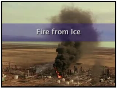
      7 months ago, on February 16, 2007, 2.09pm, a big blast in Valero McKee Refinery in Sunray, Texas, 65 miles North of Amarillo. This major event has occurred in the Propane Deasphalting unit and caused three workers critically injured, and the major refinery shut down for two months.

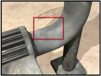
      CSB has conducted investigation and release it final report on July 09, 2008. As per the studies, the major cause of this accident was foreign material inhibit proper isolation resulted water passing a isolation valve, ice formed in a isolated dead leg during cold weather and ice expansion [1] caused the dead leg piping cracked. Once the ice is melted, large amount of propane is leak through the crack and jet fire form. Jet fire further damage another flange and generated another jet fire impinged on a major non-fireproofed piperack. Finally piperack collapsed resulted major release of flammable hydrocarbon and serious plant fire.

      [1] : Why does water expand when it freezes?


      Dead leg piping cracked due to ice expansion


      Pressurized propane leak via crack

      CSB has released a 13 minutes CSB Safety Video briefly described about this accident.


      Valero Refinery Propane Fire Safety Video

      Details investigation report can be downloaded via this link (click here).

      From the investigation, several observations in API code & standard have been reported :
      • API guidance does not specifically discuss the use of remotely operated Shut-off valve (ROSOV) in controlling jet fires
      • API recommends structural steel fireproofing upto 50 feet. However, the CSB investigation found the fire damage can reach 77 feet.
      • Radiation caused the LPG storage external paint blistering as a result of operator could not initiate the deluge system on LPG tank due the valve is too close to the incident area
      • Hazard Analysis has not evaluated the storing of Chemical product i.e Chlorine in the plant. API do not require hazards analysis from nearby unit when locating fire water deluge valves
      There are several lesson learned and key recommendations :
      • identification of infrequently used piping or equipment subject to freezing
      • establishment freeze protection written program
      • specific approaches to eliminate freeze hazards
      • periodic inspections
      • addresses jet fire scenarios, use of protective fireproofing and other measures (e.g., emergency isolation valves, depressuring systems)
      • Use remotely operated Shut-off valve (ROSOV) and interlocked equipment controls for quick isolation
      • effective deluge system activation during emergencies
      • replacing chlorine with biocide for cooling water
      Recommended :
      Subscribe FREE - Processing Magazine

      Most of above recommendations have also been discussed in "Protective Measures against FIRE other than Pressure Relief Device (PRD)" and "Some Comments on Providing External Insulation as Protective Measure against FIRE".

      Those design trying to eliminate fire scenario in the plant as discussed "Extra Caution When Eliminating Overpressure by Fire Attacks" shall be addressed carefully and extra effort shall be put in .

      Source :
      CSB - Valero Refinery Propane Fire
      Report: Valero refinery fire caused by leak

      Related Post