Showing posts with label HYSYS. Show all posts

Sunday, August 1, 2010

HYSYS OLGA Link User Guide

Recommended :
This user guide details all the procedures you need to work with the OLGA Link extension which will help you learn how to use OLGA Link efficiently, this manual thoroughly describes the views and capabilities of the OLGA Link as well as outlining the procedural steps needed for running the extension. The basics of building a simple OLGA Link model is explored in the tutorial (example) problem. The case is presented as a logical sequence of steps that outline the basic procedures needed to build an OLGA Link case. This guide also outlines the relevant parameters for defining the entire extension and its environment. Each view is defined on a page-by-page basis to give you a complete understanding of the data requirements for the components and the capabilities of the extension.

The OLGA Link User Guide does not detail HYSYS procedures and assumes that you are familiar with the HYSYS environment and conventions. If you require more information on working with HYSYS, please refer to the HYSYS Manuals. Here you will find all the information you require to set up a case and work efficiently within the simulation environment. Throughout this document, when describing OLGA keywords that are required in the *.inp file for your OLGA model, capital letters will be used for the complete keyword. For example BOUNDARY represents the keyword and specification of a boundary node and its relevant boundary conditions in the OLGA model. Throughout this document (and when you are using distributed computing with one computer for HYSYS and the OLGA Link, and another computer for the OLGA software), you will see the reference to the HYSYS PC (local computer) and the OLGA PC (remote computer).

Download

Sunday, June 6, 2010

Background Theory in Equipment Sizing Using HYSYS


Process engineering design involve preliminary equipment sizing during initial conceptual phase. It is mainly to identify the magnitude of major equipment potentially install in a plant. This is rather important during conceptual phase as equipment dimensioning will provide sufficient key information for budgetary costing which possibly provide direction in Process Engineering Design. 

Recommended :
- Subscribe FREE - Chemical Engineering
- Tips on Succession in FREE Subscription

Process simulation is commonly conducted for all phases of design e.g. Preliminary Design, Basic Design, Front-End Design, Detailed Design, etc. Process simulation enable production of heat and material balance and provide basic process parameters for equipment specification and sizing. Conventionally equipment sizing is conducted manually and vendor preliminary sizing program / software. Transfer of process parameters to vendor software or spreadsheet will require time and effort and also subject to erroneous risk of data transfer. Therefore Process Simulation provider have taken extra effort to provide additional equipment sizing utilities in the Process Simulator to aid Process Engineer to identify system capacity and rule out technical not feasible process option. ASPEN HYSYS have done the same to assist user.


The following document is a HYSYS SIZING guide which provide information in using Sizing Utilities and provide the theories and equations used in the sizing Utilities. It is particularly important for an HYSYS Sizing Utilites user have clear understanding of the utilities background and limitation.

Sunday, May 16, 2010

Simulation of Gas Power Plant Using HYSYS

The basic principle of the Combined Cycle is by burning gas in a gas turbine (GT) produces electric power by a coupled generator and routing hot exhaust gases through a water-cooled heat exchanger produces steam, which can be turned into electric power with a coupled steam turbine and generator.

Recommended :
Subscribes to FREE Hydrocarbon Processing

This set-up of Gas Turbine, waste-heat boiler, steam turbine and generators is called a combined cycle. This type of power plant is being installed in increasing numbers round the world where there is access to substantial quantities of natural gas. This type of power plant produces high power outputs at high efficiencies and with low emissions. It is also possible to use the steam from the boiler for heating purposes so such power plants can operate to deliver electricity alone

Efficiencies are very wide ranging depending on the lay-out and size of the installation and vary from about 40-56% for large new natural gas- fired stations. Developments needed for this type of energy conversion is only for the gas turbine. Both waste heat boilers and steam turbines are in common use and well-developed, without specific needs for further improvement.


The primal objective of this report is to show the efficiency into simulate a Gas Power Plant with Combined Cycle technology with HYSYS software; and to optimize the process to get the biggest possible economic benefit, making changes in the feed variables of the combined cycle plant. The data of this project are based on the document of the Department of Energy of United States.

Monday, May 10, 2010

ASPEN PIPESYS MANUAL

Aspen PIPESYS integrates powerful capabilities for single and multiphase pipeline flow modeling into Aspen HYSYS. Aspen PIPESYS enables users to:
  • Rigorously model single phase and multiphase flows
  • Perform forward and reverse pressure calculations
  • Determine changes in pipeline flow or conditions and their effect on an entire plant using a Aspen HYSYS simulation
  • Compute detailed pressure and temperature profiles for pipelines that traverse irregular terrain, both onshore and offshore
  • Perform special analysis including pigging slug size predictions, erosion velocity limits, and the likelihood of severe slugging in vertical or near-vertical risers
    Perform sensitivity calculations to determine the dependency of system behavior on any parameter
    Determine the possibility of increasing capacity in existing pipelines based on computational effects, pipeline effects, and environmental effects
Following are list of PIPESYS manual available for easy assess :

ASPEN PIPESYS 2002 Getting Started

ASPEN PIPESYS 2003 Installation Guide
ASPEN PIPESYS 2003 Tutorials
ASPEN PIPESYS 2003 User Guide

ASPEN PIPESYS 2004.1 Getting Started

ASPEN PIPESYS V7 Getting Started

If you found any documents related to ASPEN PIPESYS and/or available FREE for all, you are encourage to share within our community. You may drop a note via email or comment. Please include your nickname.

Related Topic

Wednesday, December 30, 2009

AspenONE Interface Using 9 Different Languages now !


Aspen product including HYSYS and FLARENET used to have English interface. Nevertheless, engineer and operators from certain countries are normally not used to English language and this lead to many error in understanding and operation of Aspen products. Typical countries are China, Japan, Korean, Brazil, Latin American countries, etc.


Aspen aware of this issue and has taken a big step in making their product interface using 9 different languages. There are
  • Chinese
  • French
  • German
  • Italian
  • Japanese
  • Korean
  • Portuguese
  • Russian
  • Spanish
You may download these language packs for the localized products from the AspenTech Support Center.

Related Topic

Monday, March 9, 2009

Oil Characterization Method in HYSYS

Recommended :
Tips on Succession in FREE Subscription
Subscribe FREE - Processing Magazine

The petroleum characterization method in Aspen HYSYS converts laboratory analysis of condensates, crude oils, petroleum cuts, and coal-tar liquids into a series of discrete hypothetical components. These petroleum hypo components provide the basis for the property package to predict the remaining thermodynamic and transport properties necessary for fluid modeling. Aspen HYSYS produces a complete set of physical and critical properties for the petroleum hypo components with a minimal amount of information. However, the more information you supply about the fluid, the more accurate these properties will be, and the better Aspen HYSYS will predict the fluid's actual behavior.

Sunday, February 8, 2009

Dynamic Modeling - Process Control and Design Applications

Display problem ? Click HERE

Recommended :
Tips on Succession in FREE Subscription
Subscribe FREE - Processing Magazine

Dynamic modeling is a common tool for evaluation of plant operating conditions and control strategies. It can be used during design, prior to start-up, campaign changes, normal plant operation and prior to shutdown to understand the performance. It prepare design and operator to understand the potential problem and get ready to handle and manage the situation. High fidelity dynamic simulators has been developed for the process industries provide a solid basis for accurate modeling of the dynamic transitions. Nevertheless, development of custom components (for specific features of the process and measurement system) is often needed to provide a realistic model of the plant.

This paper presents a development approach and application of a dynamic model for the plant off-gas system, characterized by the complex structure and strong interaction of the production units with fast dynamics and sharp unexpected changes of the process pressure.


The model was developed in several phases using a HYSYS dynamic simulator. Initially, the model for the existing plant configuration, in nominal operational mode, was created; i.e. the plant emergency pressure relief devices that required custom modeling were not included. This model was validated using the plant data historian and was used for evaluation of the process dynamics and improvement of the existing control system. Then the model for the thermal oxidizer unit (a redesign option to decrease plant emissions) was added. This model was used in the design of the advanced control strategies for the modified process and thermal oxidizer itself. These strategies were tested for various scenarios of plant events and the expected plant unit interactions were evaluated. Finally, as the confidence of Plant Manufacturing grew, the model was extended with the custom pieces of the pressure relief devices (existing and new projected ones) and was used for development and justification of the plant vent system redesign.

Download

There is a Dynamic Simulation manual available in ASPEN HYSYS. You may obtain your copy. Read more in "Useful Documentation for HYSYS ...".


Related Topic

Sunday, January 25, 2009

Depressuring Flow - Quick Manual Method

Display problem ? Click HERE

Recommended :
Subscribe FREE - Processing Magazine

Depressuring system is provided in Oil and gas, Gas & LNG plant, etc to evacuate the inventory from process system as fast as possible so that the reduced internal pressure stresses is kept below the rupture stress. This has been discussed in "Depressuring within 15 minutes no longer applicable ?". Nevertheless, quick depressuring may lead to other problem such as low temperature embrittlement, excessive noise and vibration, etc. Depressure a high pressure would lead to low temperature of depressured system and failure due to low temperature embrittlement. Higher the depressuring rate, lower the temperature can be experienced by depressured system. Thus, the restriction orifice (RO) downstream of Blowdown Valve (BDV) in depressuring system primarily is to limit flow so that the temperature will not drop below the allowable lowest temperature limit of material. This has been discussed in "Don't misunderstood depressuring".

Although depressuring shall be implemented within the shortest time possible, excessive depressuring may potentially lead to damage to equipment such as compressor seal, solid bed, etc. Thus, there are two type of depressuring as discussed in "Controlled and Non-controlled Type Depressuring". Nevertheless, it is emphasized again here, depressuring system shall be designed to bring plant to safe level without any tolerance.

Many depressuring systems are designed to depressure the system within 15 minutes follow recommendation in API 521. Nevertheless, one shall take note that the 15 minutes is sort of arbitrary and may be good for some system and configuration. Thus, in most recent API STD 521, the requirement has slightly changed where a depressuring system shall be designed such that the stress induced by internal pressure of a system is lower than stress allowable by the system. This may lead to shorter depressuring time as discussed in "Depressuring within 15 minutes no longer applicable ?".


Depressuring can be conducted using simple depressuring module in process simulator such HYSYS, PRO-II, etc. One shall understood there are limitation and accuracy issue in above mentioned depressuring modules and shall be used with care. There are other depressuring simulator such as LNGDYN by TECHNIP, BLOWDOWN by Imperial College, etc which are calculated rigorously and tested with real plant data. It is always advisable to use these simulator for specific case.

Assumption
In this post, a manual depressuring method is introduced. This method is first introduced by Grote and are derived base on following assumptions :

i) Critical flow throughout entire depressuring process
ii) Constant mass flow throughout entire depressuring process
iii) System being depressured is maintained as gaseous throughout entire depressuring process
iv) Constant temperature, molecular weight and compressibility

Methodology
Following is the derivation of the manual equation.


Concluding Remark
Equation [5] may be used for manual depressuring if a system inventory (initial mass, M0), depressuring time (t), initial (P0) and final pressure (P) are are known. One shall check the assumptions are valid before it is used. This equation may be used as quick method to determine the depressuring flowrate for quick estimate, however it is not recommended during detailed design.


Wednesday, November 26, 2008

Obtain HYSYS Worldwide Support Information Instantly

Display problem ? Click HERE

Some time you may experience problem or technical issue with HYSYS operation, or you may found some bugs in the HYSYS, it is common that you can make necessary report to Aspen HYSYS support center to looks for solution. Aspen HYSYS has a team operate world wide to support all Aspen HYSYS registered users.

Aspen HYSYS has many support centers i.e. U.S., Canada, Mexican, Venezuela, France, UK, Egypt, South Africa, Malaysia, Singapore, Australia, etc. You may sometime would like quick information for the contact. HYSYS has one unique support email address : esupport@aspentech.com

However, you may like to obtain other information i.e contact number, fax number, etc for a particular nearest support center. This is especially important when you are outstation. One of the quickest way is from the HYSYS software itself. HYSYS has built-in these information in the HYSYS itself. See below image.


(Click to view larger image)

To launch this utility, just simply open the Help | About HYSYS..., pop-up display will show the HYSYS version/build. Then click the Technical Support at the bottom. You can obtain information for phone number, fax number, email address, toll free number, international toll free number, website address and support website address for all latest support centers.


Related Topic

Tuesday, November 25, 2008

HYSYS Version & Build number

Display problem ? Click HERE

HYSYS release is normally follow it build number. i.e version 3.2, the build number is 5029. For some of the HYSYS version i.e. 2004, there are several builds released for the same versions. Following is a simple listing of build for references.

Build Version
7020 V7.0
6924 2006.5 with CP3
2006.5 with CP2
2006.5 with CP1
2006.5
6729 2006 with CP2
2006 with CP1
6728 2006
6612 2004.2 with CP5 + Patch 6
2004.2 with CP5
2004.2 with CP4
2004.2 with CP3
2004.2 with CP2
2004.2 with CP1
2004.2
6510 2004.1 with CP1
2004.1
6150 2004
5029 3.2
4815 3.1
4602 3.0.1
3874 2.4.2
3870 2.4.1
3806 2.2.2
3797 2.2
3216 2.1.3
3198 2.1.1

This post is sort of follow-up post from earlier post "Incompatibility HYSYS Version & Its File...What to do ?", which has discussed the way to identify HYSYS version/build. One of the important information is the cumulative patches should match with the correct version. If you have version 2006.5, you should ensure you have installed CP3 to ensure proper operation of HYSYS 2006.5.


Friday, November 21, 2008

Incompatibility HYSYS Version & Its File...What to do ?

Display problem ? Click HERE

Recommended :
Tips on Succession in FREE Subscription
Subscribe FREE - Processing Magazine


Some time you received an HYSYS file (ABC.hsc) from contractor or client, you open the file using a particular version (i.e. HYSYS 3.2), you may experience the HYSYS failed to open the file. Reason being you are using older version/build of HYSYS (i.e 3.2 ) to open a newer version/build of HYSYS (i.e 2006).

There are several questions may be raised :

i) How to know which version/build of HYSYS that you are using ?
ii) How can you know which version/build of HYSYS a case was created ?
iii) How to open a newer version/build of HYSYS with older version/build of HYSYS ?


HYSYS version
To know which version of HYSYS you are using, just simply open the Help | About HYSYS..., pop-up display will show the HYSYS version/build. The following image shows it is HYSYS version 3.2 (Build 5029).


HYSYS Version of Created File
To know which version the file was created, first you need to make small changes in HYSYS Preferences. Click Tools | Preferences, the Session Preferences pop-up will be displayed. Click Files tab and select HYPROTECH file Picker on the top, then click the Save Preferences Set. See


Now click the File | Open | Case, the file open pop-up is displayed. You will notice the version / build of the file created in HYSYS.


(Click to view large image)

You may also get similar information when you click the File | Save As. See below image.


(Click to view large image)


Open File Created in Newer Version with Older Version of HYSYS
The topic has been discussed in earlier post "Open HYSYS File in Older Version of HYSYS".

To get more tutorial and information related to HYSYS, check out "Useful Documentation for HYSYS ...".

Related Topic

Friday, November 14, 2008

Mass Heat of Vaporization in HYSYS only for Pure Component

Display problem ? Click HERE

Recommended :
- Tips on Succession in FREE Subscription
- Subscribe FREE - Hydrocarbon Engineering

Since the released of this article "Determine Latent Heat for Multi-Component and Relieving Area Using Rigorous Method in HYSYS", a few young engineers raised a question. The proposed method does not work for pure component i.e. pure propane. How shall i obtain the latent heat of pure component using HYSYS ?

The proposed method in "Determine Latent Heat for Multi-Component and Relieving Area Using Rigorous Method in HYSYS" is typically use to handle system with multi-component with large ranging of boiling point. It is typical useful for crude, naphtha, gasoline, condensate, etc. However, the propose method can not be used for pure component as it has only single boiling point at one pressure i.e. 152.4 Btu/lb at 100 psia for pure propane.


To obtain the latent heat of vaporization for pure component from HYSYS, it is pretty simple. From stream properties tab, latent heat of vaporization (Hvap) will be the Vapor Mass Enthalpy (Hv) minus Liquid Mass Enthalpy (Hl). Refer to above image. Hv = - 1032.6 Btu/lb, Hl = -1185 Btu/lb, thus Hvap = -1032.6 - (-1185) = 152.4 Btu/lb at 100 psia.


Another way is to read the Latent heat of Vaporization (Hvap) directly from properties tab. See above image. Mass Heat of Vap (Btu/lb) = 152.4 Btu/lb.

Important Note :
For pure component, latent heat of vaporization can be obtained by Vapor Mass Enthalpy (Hv) minus Liquid Mass Enthalpy (Hl).

For multi-component, latent heat of vaporization is NOT advisable to obtain by Vapor Mass Enthalpy (Hv) minus Liquid Mass Enthalpy (Hl). Rigorous method proposed in "Determine Latent Heat for Multi-Component and Relieving Area Using Rigorous Method in HYSYS" can be used.

Related Topic

Tuesday, November 11, 2008

Adjusted Method For Compressor Settle Out (with Vapor & Liquid) Using HYSYS

Display problem ? Click HERE

Since the release of "Simple Method For Compressor Settle Out Using HYSYS", some readers of Chemical & Process Technology raised a question. The proposed method has considered all in VAPOR, how shall this method apply in case of present of VAPOR and LIQUID in Compressor Suction drum and Air Cooler Downstream ?

It is correct that the simple method is simplified version for VAPOR only Settle out condition. Nevertheless, minimum adjustment to the method enable the method to be used for condition with VAPOR and LIQUID. First refer to following image.


Step 1 : Compressor Suction. Estimate physical volume of vapor (Vv1) and liquid (Vl1).
Step 2a : Compressor Suction. Separate Compressor Suction Inlet (stream 1) with 2-phases (vapor & Liquid) with Separator unit operation.
Step 2b : Copy Compressor Suction Inlet Vapor (stream 2) condition and composition to a new stream Actual Compressor Suction Inlet Vapor ((stream 4). Adjust Mass flow of this stream until the Actual Volumetric Flow equal to Vv1.
Step 2c : Copy Compressor Suction Inlet Liquid (stream 3) condition and composition to a new stream Actual Compressor Suction Inlet Liquid (stream 5). Adjust Mass flow of this stream until the Actual Volumetric Flow equal to Vl1.
Step 2d : Mix Actual Compressor Suction Inlet Vapor (stream 4) and Actual Compressor Suction Inlet Liquid (stream 5) to form Compressor Suction (stream 6).

Normally the Compressor Discharge stream is superheated and no liquid is expected.

Step 3 : Air Cooler Downstream. Estimate physical volume of vapor (Vv3) and liquid (Vl3).
Step 4a : Air Cooler Downstream. Separate Air Cooler Downstream Outlet (stream 7) with 2-phases (vapor & Liquid) with Separator unit operation.
Step 4b : Copy Air Cooler Downstream Outlet Vapor (stream 8) condition and composition to a new stream Actual Air Cooler Downstream Outlet Vapor (stream 9) . Adjust Mass flow of this stream until the Actual Volumetric Flow equal to Vv3.
Step 4c : Copy Air Cooler Downstream Outlet Liquid (stream 10) condition and composition to a new stream Actual Air Cooler Downstream Outlet Liquid (stream 11). Adjust Mass flow of this stream until the Actual Volumetric Flow equal to Vl3.
Step 4d : Mix Actual Air Cooler Downstream Outlet Vapor (stream 9) and Actual Air Cooler Downstream Outlet Liquid (stream 11) to form Air Cooler Downstream (stream 12).

The remaining steps are same as "Simple Method For Compressor Settle Out Using HYSYS" by adjusting Settle Out Cond Actual Volumetric Flow same as Vv1+Vl1+V2+Vv3+Vl3.

Related Topic

Thursday, November 6, 2008

Simple Method For Compressor Settle Out Using HYSYS

Display problem ? Click HERE

Recommended :
Subscribe FREE - Processing Magazine

Compressor emergency blowdown is commonly initiated after compressor system shutdown. The compressor shutdown will also lead to Compressor System Suction shutdown valve (SDV) and Discharge SDV to shut close and the anti-surge and/or capacity control valve open. Compressor discharge with high pressure and hot, air cooler and downstream high pressure and cold and suction vessel low pressure and cold will be settled-out prior to blowdown.

How to estimate the settle out condition ?

Settle-out of compressor system can be conducted using HYSYS. The main concept is constant mass and volume before and after settle-out. It is assumed the settle out is carried out adiabatically.

Following are some steps can be used to obtain the settle-out condition. Let start with following image.


Step 1 : Calculate physical volume of Compressor Suction (V1), Compressor Discharge (V2) and Air Cooler Downstream (V3).

Step 2 : Setup the system as per above image by correct Compressor Suction, Compressor Discharge and Air Cooler Downstream operating condition and composition.

Step 3 : Adjust Compressor Suction, Compressor Discharge and Air Cooler Downstream Mass flow until the respective Actual Volumetric Flow same as V1, V2 and V3.

Step 4 : Set Balance (BAL-1) for Mole & Heat

Step 5 : Adjust Settle-out Cond stream pressure until the Actual Volumetric Flow same as V1+V2+V3.

Thus, the settle out condition can be extracted from the Settle-out Cond stream.

Do you aware of other method ? Why not share with us ?

Related Topic

Tuesday, November 4, 2008

Saturate Dry Gas With Water in HYSYS Using SATURATE Extension

Display problem ? Click HERE

Wetting a dry gas using 3-phase Separator unit operation in HYSYS has been discussed in "Saturate Dry Gas With Water in HYSYS". It is a simple but ordinary way and useful. Aspen HYSYS (previously Hyprotech) has generated a simple extension called SATURATE extension to perform same function. See below image.


Locate SATURATE Extension
The SATURATE extension does not come with HYSYS installation file. It can be downloaded from ASPENTECH Support Website. Click here to locate the HYSYS extension. (for register user only).

Register & Access SATURATE Extension
Once the SATURATE extension is downloaded, it shall be registered in HYSYS. Unzip the saturate.edf and saturate.dll files to a convenient directory on your hard disk. Go to Tools … Preferences, then choose the Extensions tab, click the Register an Extension button, then navigate to the location of the saturate.dll file. Local Administrator privileges are required in order to register an extension. The Saturate Stream Unit extension should then appear under the Extensions category of the Add Operation window. (Accessible via Flowsheet … Add Operation, or by pressing F12.)


Obtain Water Content
Once the SATURATE extension is open, above tab will be shown. Just set the the unit to lb/mmcf at Standard condition, the water content in lb/mmscf can be found.

Find Under Saturate Water Content
If one to find the Water Content at 80% Humidity, just simply change the Humidity input to 80. Water content at under saturate condition will be shown.

Applicability
This extension only support HYSYS 2.4.1 onwards.


Related Topic

Sunday, November 2, 2008

Saturate Dry Gas With Water in HYSYS

Display problem ? Click HERE

A loyal reader in Chemical Process Technology raised a question. I have a dry gas composition. As the gas is produced from reservoir, it is saturated with water. How to simulate in the HYSYS simulator ? How to calculate water content in wet gas ?

Recommended :
Subscribe FREE - Plant Services

From hydrocarbon - water equilibrium analysis, you will find that as you increase water content in dry gas, the water will mix with dry gas until the dry gas is saturated with water. Once it is saturated with water, any addition of water into the water saturated gas (normally called wet gas) will knock-out as free water in aqueous phase. This can be easily modeled in any process simulator like HYSYS.

Below image shows Dry gas stream is mix with Water in a 3-phase Separator unit operation. To saturate the Dry gas with water, the only requirement is increase the Free Water flow until the aqueous flow (Free Water) starts to knock off free water. In this case, an ADJUST unit is used to adjust the water flow until zero flow.


To find water content (in lb/mmscf), first check out the Water Mass Flow in Wet gas from composition, change the basis to mass flow. See following image.


Then find the Molar flow in MMSCFD. See following image.


In above example, the Water Mass Flow is 1233.6 kg/h (2719.6 lb/h) and Molar Flow is 1005 mmscfd. Thus,

Water content = (2719.6 x 24) / 1005 = 64.93 lb Water / mmscf Gas.

If you have better method, let us know.

Related Topic

Wednesday, August 27, 2008

Depressuring - Save Some Time in HYSYS - FLARENET Iteration

Display problem ? Click HERE

Recommended :
- Tips on Succession in FREE Subscription
- Subscribe FREE - Processing & Control News

"I was doing Depressuing using HYSYS and flare network back pressure calculation using FLARENET for conventional Blowdown valves with restriction (BDV/RO). Peak flow of Depressuring unit in HYSYS which obtained from initial depressuring and based on initial depressuring pressure to Atmospheric pressure, is used as input to FLARENET.

I have two questions :
What I really concerned is back pressure calculated from FLARENET is higher than ATM, is the back pressure will affect the peak flow ?

What I had done for those cases is to assume a back pressure in HYSYS to calculate the peak flow and input it into FLARENET. Newly calculated back pressure from FLARENET will be re-enter into HYSYS depressuring unit to recalculate new peak flow in HYSYS. Above will be iterated until both of back pressure and peak flow are match in HYSYS and FLARENET. Am i in right track ?"

Above was a question raised by an engineer who was conducting plant blowdown and flare network studies.

First far most important thing is that there will be total plant or segregated zone blowdown. This type of blowdown will results simultaneous opening of all BDVs within a zone and simultaneous blowdown of multiple sections. One shall not consider SINGLE BDV opening ONLY. Simultaneous blowdown will results high total blowdown rate and induced high back pressure to each BDV / RO within the blowdown zone.

In many events, the flow passing the RO is CRITICAL flow where the back pressure from flare network is lower than the fluid critical pressure (Pc). Read more in "A refresh to Process Engineer on few phenomenons in restriction orifice". Under critical flow condition, the back pressure has no impact to the flow rate passing through the RO (assume backpressure does not affect the vena contracta cross sectional area). Thus, peak flow calculated in HYSYS depressuring unit considering backpressure of ATM is still remain same if the backpressure (Pb) is lower than critical pressure (Pc).


However, for many rare cases when the system pressure is low, hence the critical is much lower. This potentially results back pressure high than critical pressure and cause SUBCRITICAL flow condition. Under this condition, backpressure has impact to the peak flow calculated by HYSYS.

Knowing back pressure may affect peak flow under subscritical flow condition, some level of checking and iteration may required.

Iteration as proposed above could be very time consuming and not all the BDV/RO required iterate update. Infact only those BDV/RO experiencing Subcritical flow would need to involve in the iteration process.

The following steps may be considered :

i) For initial step, use ATM in HYSYS for depressuring to estimate the peak flow
ii) Peak flow estimated in HYSYS will be entered into FLARENET to calculate back pressure at each BDV/ROs.
iii) Compare each BDV/RO Critical pressure (Pc) and Back pressure (Pb). If Pc is higher than Pb, that particular BDV/RO need not involve in the iteration.
iv) Identify those BDV/RO with Pc less than Pb. Re-adjust back pressure in HYSYS base on calculated Pb from FLARENET to obtain a new peak flow.
v) Reenter and rerun in FLARENET.
vi) Repeat step (iii) to (v) till backpressure in HYSYS and FLARENET are matched.

Above will significantly reduce the iteration time.

Related Topic

Friday, August 15, 2008

Control System Development with HYSYS Dynamic Simulation

Display problem ? Click HERE

Recommended :
- Tips on Succession in FREE Subscription
- Subscribe FREE - Hydrocarbon Engineering

Dynamic simulation is a tools to assist you in design, optimize and operate your plant. It helps to understanding the behavior of your plant and healthier of a control system in achieving the design control. Many of you may have heard about the capability of Dynamic simulation in ASPEN HYSYS. Some of you may have tried to make use this capability. For those who has NO experience at all or those would like to refresh their mind in dynamic simulation using ASPEN HYSYS, the following tutorial is a pretty good tutorial for learning and refreshing.

Control System Development with HYSYS
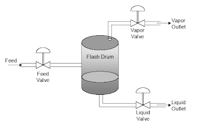
This is a tutorial on the development of dynamic simulations using ASPEN HYSYS which based on implementing three conventional PID control loops on a single-stage flash drum unit for a multicomponent, non-ideal feed stream.


The steps in the development process includes :
  1. steady-state design and simulation
  2. specifying dynamic characteristics of process equipment
  3. switching the simulation over to dynamics mode
  4. adding feedback controllers to the simulation
  5. adding strip-chart displays
  6. carrying out dynamic tests and fitting transfer functions
  7. tuning the controllers
Download Tutorial for Control System Development with HYSYS

There is a Dynamic Simulation manual available in ASPEN HYSYS. You may obtain yours copy. Read more in "Useful Documentation for HYSYS ...".

Related Topic

Thursday, July 31, 2008

Catalytic Distillation Process Simulation using HYSYS

Display problem ? Click HERE

Recommended :
- Subscribe FREE - Processing Magazine
- Tips on Succession in FREE Subscription

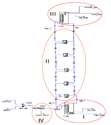
A catalytic-distillation process for the production of t-amyl-methyl-ether (TAME) from methanol and isoamylenes was simulated by developing the process model as a combination of unit operations from HYSYS operations palette. Geometrical characteristics of catalytic-distillation column are those of an industrial pilot plant and the results of simulation were compared with experimental data. The experimentally determined reactions kinetics was applied in the model. UNIQUAC-UNIFAC model equations were selected for the vapour-liquid equilibrium.

Catalytic Distillation Process Simulation using HYSYS

This paper presents a theoretical study for the modelling of reactive distillation column operation in t-amyl-methyl-ether (TAME) synthesis. The simulation procedure is based on a mathematical model considering chemical reaction kinetics for the main reactions and the vapour-liquid equilibrium. Phase contact in the reaction zone is described with the back-flow cell model.


The problem statement in HYSYS.Process environment was made considering three zones for the catalytic distillation column (rectifying, reaction and stripping). Constructive and operational characteristics of the column are specified as a consequence of the parametric study: reaction zone position, feed position and reflux ratio, in order to obtain maximum yield for the transformation of C5 reactive olefins in the pilot plant. The simulation results are in good agreement with experimental data obtained in the experimental pilot plant at SNP PETROM, INCERP Ploiesti subsidiary. The quality of the results obtained in this paper is limited by the uncertainty introduced by the phase hydrodynamics in the reaction zone the phase equilibrium hypothesis.

Read more here...

Related Topic