Showing posts with label Oil and Gas. Show all posts

Thursday, August 12, 2010

Design guideline for subsea oil systems

Design and operating guidelines for subsea oil systems have been developed to ensure the control of hydrates, wax, and other solids, which may impede flow. System designs are primarily driven by the need to avoid the formation of a hydrate plug in any portion of the system. Remediation of hydrate plugs may require system shut-in for weeks or even months. Design and operation guidelines for wax management are also well developed. Asphaltenes present a new challenge to subsea system design and operation. A number of projects now under development (Europa, Macaroni) are likely to experience some asphaltene deposition in flowlines and wellbores. Strategies have been developed to manage asphaltenes, but have not yet been tested in the field. The design and operating guidelines for control of solids in subsea oil systems are a product of the flow assurance process.

by S. E. LORIMER & B. T. ELLISON, Shell Deepwater Development Inc.

Download

Related Topic

Sunday, May 16, 2010

Injection Water Velocity Limit To Minimize Corrosion & Promote Extended Service Life

Earlier post “
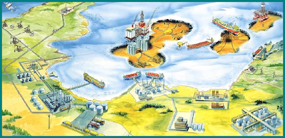
Seawater Treatment & Injection For Well Maintenance & Increase Productivity” discussed about the water source and its associated water injection treatment. Seawater will be filtered with coarse and fine filters to remove particles smaller than 2 micron with 98% removal efficiency. Filtered seawater will be deaerated to bring the Oxygen concentration down to 20 ppb. Oxygen scavenger is then injected to further reduce the Oxygen concentration down to 10 ppb in order to reduce corrosion to cost effective level. Chlorine is injected to injection water to avoid bacteria and alga growth.


Residue Oxygen in injection may still result corrosion in the pipeline. How much it affect the corrosion of Carbon steel pipeline ? Present of Chlorine is known further increase corrosivity of injection water. How this impact the corrosion water ? Increase of water velocity in pipeline will increase flow induced erosion of pipeline. Simultaneous erosion (flow induced) - corrosion (Oxygen & Chlorine) present in the pipeline. How water velocity affect corrosion ? What is the water velocity limit ? This post will present a water velocity limit with varies of oxygen concentration (and Chlorine content) in water .

Oxygen corrosion in water injection pipeline is controlled by diffusion rate of Oxygen into Cathodic with following reaction :


Steel is corroded on the Anodic side with following reaction :


Water Injection Velocity Limit
Chlorine Free
water injection velocity limit (Vmax)of Carbon steel pipeline is :


With Chlorine concentration of 0.5 ppm
water injection velocity limit (Vmax)of Carbon steel pipeline is :

where
CA = Corrosion Allowance (mm)
Y = Life span (years)
CO2 = Oxegen concentration (ppb)
T = Seawater temperature (degC)
ρw = Seawater density (kg/m3)

Example
Refer following figures for water injection velocity limit (m/s) versus oxygen level (ppb) with Chlorine free and 0.5 ppm Chlorine.


Above figures was based on

Corrosion Allowance, CA = 3.0mm
Life span (years), Y = 20 years
Seawater temperature, T = 25 degC
Seawater density, ρw = 1030 kg/m3

At 20 ppb of Oxygen concentration, the velocity limit is 5.7 m/s (Chlorine free) and 2.6 m/s (Chlorine = 0.5 ppm).

At 10 ppb of Oxygen concentration, the velocity limit is 12.2 m/s (Chlorine free) and 5.6 m/s (Chlorine = 0.5 ppm).


Ref :
1)    J.W. Oldfiedl, G.L. Swales, B.Todd, “ Corrosion of Metals in Deaerated Seawater”, Proc. Of the 2nd Corrosion Conference, held Jan, 1981
2)    J.M. Drugli, T. Rogne, “ Effect of Oxygen and Chlorine Content on the Corrosion Rate of Carbon Steel Welds in Injection Water” CORROSION/93 paper no 65
3)    Mamdouh M. Salama, “Erosion Velocity Limits for Water Injection Systems”, 1993

Related Topics 

Sunday, May 9, 2010

Seawater Treatment & Injection For Well Maintenance & Increase Productivity

Water injection is common applied in maintaining crude reservoir to increase crude productivity. For offshore facilities, seawater is commonly lifted and treated for water injection purpose. The water injection rate is subject to reservoir condition and crude production. Particle present in seawater potentially results formation blockage and reduce injectivity. Oxygen present in seawater potentially results severe corrosion of transfer pipeline and injection tubing. Alga and bacteria present in seawater may potentially growth result corrosion and formation blockage. Therefore seawater use for injection shall be treated prior transfer and injection.

Seawater Treatment
Seawater used for water injection will goes through a series of treatments :
  • Filtration - remove particles
  • Deaeration - remove oxygen
  • Chemical injection - prevent foaming, corrosion, alga / bacteria growth
Filtration
Seawater lifted will pass through filtration package. The filtration package commonly consist of two levels of filtration. First level filtration is also known as Coarse Filtration where the filter is provided to remove particle with size larger than 80-100 micron. The common required removal efficiency is 98%. The filter is normally equipped with auto-backwash facilities e.g. rotational backwash motor. Second level filtration is also known as Fine Filtration where the filter is provided to remove particle with size large than 2 micron with removal efficiency of 98%. Similarly this filter is equipped with auto-backwash facilities with the assistance of blower.


Deaeration
Seawater is aerated in ambient contains high oxygen contents. Typically the seawater is considered saturated with oxygen and this quantity is sufficient to results significant corrosion in transfer pipeline and injection tubing. Corrosion is increased with increased in quantity of oxygen in seawater. The oxygen level in the seawater is commonly deaearated down to 20-40 ppb in the deaeration column. Oxygen scavenger is injected downstream of deaeration column to further bring the oxygen level down to 10-20 ppb. Two main methods are used for deaeration :
  • Vacuum deaeration
  • Gas stripping
Chemical injection
Coagulant
Present of large quantity of small particle may results particle passing filtration, accumulates, agglomerate and finally results plugging of formation. Coagulant may be required to be injected upstream of filtration package to promote particle coagulation and filtration.

Anti-Foam
Seawater may be contaminated with hydrocarbon when it is lifted. Seawater used for processing cooling, any leakage in the seawater heat exchanger also result Hydrocarbon present in the seawater. Presented of hydrocarbon in seawater may results foaming in deaeration column. Therefore, anti-foam may be required to suppress foaming.

Biocide (Hypo-chloride)
Bacteria presents in seawater may results corrosion and alga growth which release solid waste to promote formation plugging. Hypo-Chloride is injected to prevent bacteria and alga growth. One shall take note present Chlorine is seawater may also results corrosion. Concentration subject to type of Biocide, however 5 ppm level could be good guess.

Corrosion Inhibitor

Present of Chlorine, residue bacteria and residue oxygen promote corrosion. Therefore corrosion inhibitor (CI) is injected to prevent / minimize corrosion. Concentration subject to type of CI, however 5 ppm level could be good guess.

Related Topics 

Tuesday, April 13, 2010

Introduction to Oil & Gas Production Presentation


Oil has been used for lighting purposes for many thousand years. In areas where oil is found in shallow reservoirs, seeps of crude oil or gas may naturally develop, and some oil could simply be collected from seepage or tar ponds. Historically, we know of tales of eternal fires where oil and gas seeps would ignite and burn. One example 1000 B.C. is the site where the famous oracle of Delphi would be built, and 500 B.C. Chinese were using natural gas to boil water. But it was not until 1859 that "Colonel" Edwin Drake drilled the first successful oil well, for the sole purpose of finding oil.

Recommended :

Earlier post "An Introduction to Oil & Gas Production..." has presented a handbook to provide readers with an interested in the oil and gas production industry an overview of the main processes and equipment. This handbook will also provides enough detail to let the engineer get an appreciation of the main characteristics and design issues.,

Similarly, Ta Quoc Dung has made a presentation on "Introduction to Oil & Gas Production". This presentation consists of five (5) chapters.
  1. Introduction
  2. Process overview
  3. Performance of Flowing well
  4. Artificial lift
  5. Enhanced oil recovery
Going through this presentation, it allows reader
  • to have overview of Petroleum Production Technology
  • to understand the role of Production Engineer in a Petroleum Operating Company
  • to understand production system and its onshore and offshore facilities 
  • to understand concept of inflow performance, lift performance and integrated nature
  • to understand enhanced oil recovery process


 Download

Thanks to Ta Quoc Dung

Related Topic

Monday, March 9, 2009

Oil Characterization Method in HYSYS

Recommended :
Tips on Succession in FREE Subscription
Subscribe FREE - Processing Magazine

The petroleum characterization method in Aspen HYSYS converts laboratory analysis of condensates, crude oils, petroleum cuts, and coal-tar liquids into a series of discrete hypothetical components. These petroleum hypo components provide the basis for the property package to predict the remaining thermodynamic and transport properties necessary for fluid modeling. Aspen HYSYS produces a complete set of physical and critical properties for the petroleum hypo components with a minimal amount of information. However, the more information you supply about the fluid, the more accurate these properties will be, and the better Aspen HYSYS will predict the fluid's actual behavior.

Saturday, September 6, 2008

An Introduction to Oil & Gas Production...

Display problem ? Click HERE

Recommended :
- Subscribe FREE - Chemical Processing
- Tips on Succession in FREE Subscription

Oil has been used for lighting purposes for many thousand years. In areas where oil is found in shallow reservoirs, seeps of crude oil or gas may naturally develop, and some oil could simply be collected from seepage or tar ponds. Historically, we know of tales of eternal fires where oil and gas seeps would ignite and burn. One example 1000 B.C. is the site where the famous oracle of Delphi would be built, and 500 B.C. Chinese were using natural gas to boil water. But it was not until 1859 that "Colonel" Edwin Drake drilled the first successful oil well, for the sole purpose of finding oil.


Oil & Gas Production Handbook

There are much of equipment described in standards, equipment manuals and project documentation, however, material to quickly provide reader an overview of the entire upstream area found to be pretty minimum. This is a handbook been compiled to provide readers with an interested in the oil and gas production industry an overview of the main processes and equipment. Above handbook will also provides enough detail to let the engineer get an appreciation of the main characteristics and design issues.,

Download (Click HERE)

Related Posts

Thursday, October 11, 2007

New Concept of Floating Unit - Part 2

Previous post present the concept of floating unit. This post will bring you real construction, float off, Load out and Sailing of these floating unit.

(Click photo for better view)


Construction of platform jacket (short cylinder)


(Begin installation of topsite)


(Living quarter installation)


(Construction completion is around the corner)


(Float off & Loadout)


(Sailing...)


(Installed & in Production)

More pictures...Click HERE


Related Topics :


Continue receive FREE stuff & Update.......Subscribe by Email OR RSS
Any comments / advices ?..........Drop it in comment field (below) or sent a private email to me...

Wednesday, October 10, 2007

New Concept of Floating Unit - Part 1

I have seen many Floating Production Storage Offloading (FPSO) either is new build and /or conversion from existing ship. Somehow all FPSO are in rectangle shape with rather sharp head. The other type of Floating Production Unit (FPU) which is in a rather square shape.

The following are some new type of floating platforms. There consist of Floating Accommodation Unit (FAU), Floating Drilling Production Storage Offloading Unit (FDPSOU), Floating Gas Turbine Generator Unit (FGTG) and Floating Mobile Subsea Vehicle Unit (FMSVU).

Floating Accommodation Unit (FAU)
Sevan_FAU
(Click image for better view)

Floating Drilling Production Storage Offloading Unit (FDPSOU)
Sevan_FDPSO
(Click image for better view)


Floating Gas Turbine Generator Unit (FGTG)Sevan_GTW
(Click image for better view)


Floating Mobile Subsea Vehicle Unit (FMSVU)Sevan_MSV
(Click image for better view)

All units are potable and inter-link between each and other. They can be added and relocated according operation demand.

These units have been constructed in YANTAI yard, China in 2005. Next post will includes the actual photos of these units.

Related Topics :


Continue receive FREE stuff & Update.......Subscribe by Email OR RSS
Any comments / advices ?..........Drop it in comment field (below) or sent a private email to me...