Wednesday, July 16, 2008

API Std 521 ADDENDUM, MAY 2008 - Check Out Revised Section

Display problem ? Click HERE

American Petroleum Petroleum (API) released the API Std 521, Pressure Relieving and Depressuring Systems early of 2007. As usual, there are some mistakes spotted in the this Standard. First errata that i received was dated June 21, 2007. Detail read here.

American Petroleum Petroleum (API) has released latest Addendum May 2008. Several sections in API Std 521 - ISO 23251 - Ed 5 - Jan 2007 - Pressure-relieving and Depressuring Systems have been updated in ADDENDUM, MAY 2008.

The updated sections are :
  • 5.15.7.4 Liquid cooling service (Partly revised)
  • 5.23 Overfilling process or surge vessel (Added)
  • 6.6.2.3 (Partly in revised)
  • 6.7 Disposal through common vent stack (Added)
  • 7.3.2.1.2 (Partly revised)
  • 7.3.2.3 Knockout drums venting to atmosphere (Added)
  • 7.3.2.4 Design details (Partly revised)
  • 7.3.4.1 Sizing (Partly revised)
  • 7.3.4.2 Design details (Partly revised)
  • Bibliography (Partly revised

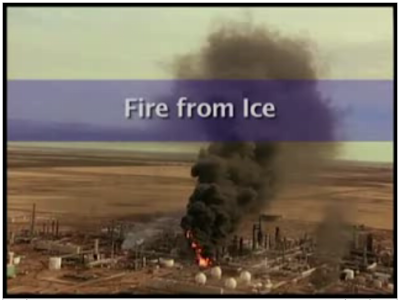
"Fire from Ice" - Lesson Learned & Key Recommendations

Display problem ? Click HERE


Recommended :
Subscribe FREE - Legal Aspects of Incident Investigation

7 months ago, on February 16, 2007, 2.09pm, a big blast in Valero McKee Refinery in Sunray, Texas, 65 miles North of Amarillo. This major event has occurred in the Propane Deasphalting unit and caused three workers critically injured, and the major refinery shut down for two months.

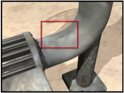
CSB has conducted investigation and release it final report on July 09, 2008. As per the studies, the major cause of this accident was foreign material inhibit proper isolation resulted water passing a isolation valve, ice formed in a isolated dead leg during cold weather and ice expansion [1] caused the dead leg piping cracked. Once the ice is melted, large amount of propane is leak through the crack and jet fire form. Jet fire further damage another flange and generated another jet fire impinged on a major non-fireproofed piperack. Finally piperack collapsed resulted major release of flammable hydrocarbon and serious plant fire.

[1] : Why does water expand when it freezes?


Dead leg piping cracked due to ice expansion


Pressurized propane leak via crack

CSB has released a 13 minutes CSB Safety Video briefly described about this accident.


Valero Refinery Propane Fire Safety Video

Details investigation report can be downloaded via this link (click here).

From the investigation, several observations in API code & standard have been reported :
  • API guidance does not specifically discuss the use of remotely operated Shut-off valve (ROSOV) in controlling jet fires
  • API recommends structural steel fireproofing upto 50 feet. However, the CSB investigation found the fire damage can reach 77 feet.
  • Radiation caused the LPG storage external paint blistering as a result of operator could not initiate the deluge system on LPG tank due the valve is too close to the incident area
  • Hazard Analysis has not evaluated the storing of Chemical product i.e Chlorine in the plant. API do not require hazards analysis from nearby unit when locating fire water deluge valves
There are several lesson learned and key recommendations :
  • identification of infrequently used piping or equipment subject to freezing
  • establishment freeze protection written program
  • specific approaches to eliminate freeze hazards
  • periodic inspections
  • addresses jet fire scenarios, use of protective fireproofing and other measures (e.g., emergency isolation valves, depressuring systems)
  • Use remotely operated Shut-off valve (ROSOV) and interlocked equipment controls for quick isolation
  • effective deluge system activation during emergencies
  • replacing chlorine with biocide for cooling water
Recommended :
Subscribe FREE - Processing Magazine

Most of above recommendations have also been discussed in "Protective Measures against FIRE other than Pressure Relief Device (PRD)" and "Some Comments on Providing External Insulation as Protective Measure against FIRE".

Those design trying to eliminate fire scenario in the plant as discussed "Extra Caution When Eliminating Overpressure by Fire Attacks" shall be addressed carefully and extra effort shall be put in .

Source :
CSB - Valero Refinery Propane Fire
Report: Valero refinery fire caused by leak

Related Post

Tuesday, July 15, 2008

Compressed Gas Incident - Awareness & Learning Fundamentals...

Display problem ? Click HERE


Recommended :
Subscribe FREE - Processing Magazine


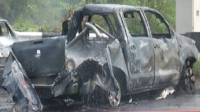
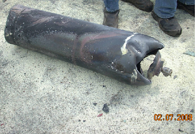
There was an incident happened recently near a factory involved 3 cars on the roads. A small truck carried 2 Acetylene gas cylinders and 2 Oxygen gas cylinder at the back caught fire in the middle of road. The cylinder on fire flew like a bullet, hit at first car, penetrated the car roof and final stopped after hit at second car front bumper. No details revealed...


Following are some photos captured for view :
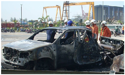


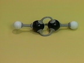
Acetylene (IUPAC name: ethyne) , C2H2, is a unstable and unsaturated triple bonded hydrocarbon in gas form. It common store as compressed gas in cylinder. Similarly an Oxygen cylinder is compressed oxygen store in cylinder. Acetylene and Oxygen are commonly used for welding (known as Oxy-acetylene welding), cutting, heat treatment and coating. As the car carried Acetylene & Oxygen gas cylinder, it is obvious that the owner use them for welding and cutting purpose.


Recommended :
Subscribe FREE - Chemical Processing

A simple Material Safety Datasheet (MSDS) for Acetylene is located here (click here). From the MSDS, acetylene is extremely flammable (low flash point) and explosive. IT MAY DECOMPOSE VIOLENTLY IN ITS FREE STATE UNDER PRESSURE IN EXCESS OF 15 PSIG.

Following is a video clip shows you how "explosive" is if Acetylene mix with Oxygen.
(If you can not view the video clip, click here to view via browser)


How "explosive" is if Acetylene mix with Oxygen

If you or your operators are handling compressed gas i.e. Acetylene, Oxygen, Nitrogen, etc, be sure you and your operators are well aware of the properties of the gases, the way to handle, transport and operate them in the safe manner. Following are collection of article that helps you to educate yourself or your operators :

Gas Cylinder Awareness Outline
The purpose of this awareness training is to help staff and students understand how compressed gas cylinders (CGC) work and how to handle them safely. The training should address the following objectives:
  • Understand the inherent dangers of compressed gas cylinders
  • Look to hazard labels, warning signs and MSDS for important information
  • Selection of appropriate PPE when working with gas cylinders
  • Know how to properly move, handle and store cylinders
  • Know what to do in case the cylinder or delivery system develops a leak (e.g., trouble-shooting and emergency procedures)
  • Know what problems can occur when installing a cylinder in a gas delivery system (e.g., installing a regulator on a cylinder)
  • Know how to check cylinders for potential problems
2.02 Compressed Gas Cylinder Program
This program contains requirements for practices designed and implemented to protect University employees from the hazards of compressed gases as identified by the University and as defined by OSHA in 29 CFR 1910, the National Fire Protection Association (NFPA) and the Compressed Gas Association (CGA).

Gas Cylinder Safety
A brief discussion on grades of gases, normal storage pressure, type of fitting and regulators used, transportation, storage, how to keep safe of compressed gases, problems related to regulators, information on fire and other aspect.

Gas Cylinder Handling & Storage
Gas cylinders are constructed and maintained in accordance with regulations of the Department of Transportation (DOT). The purchaser should make sure all cylinders bear DOT specification markings, and the contents should be legibly marked on each cylinder in large letters....

Compressed Gas Cylinder Storage and Handling
Compressed gas cylinders are used in many workplaces to store gases that vary from extremely flammable (acetylene) to extremely inert (helium). Many compressed gas cylinders are stored at extremely high pressures (up to 2,500 pounds per square inch gauge or PSIG). A sudden release of these gases can cause a cylinder to become a missile-like projectile. Cylinders have been known to penetrate concrete-block walls. If handled properly compressed gas cylinders are safe. If handled improperly, the same cylinders can present a severe hazard to you and the surrounding area.

Guidelines for Gas Cylinders
This document is an advisory text which sets out general guidelines for the safe storage and handling of gas cylinders. Further information may be obtained from the documented references and the Heath, Safety & Environment Unit. Gas cylinders are used in many University work areas. Approved methods of handling, storage and transport will ensure safe use by the University staff and contractors.

Acetylene, the Principles of Its Generation and Use
A practical handbook on the production, purification and subsequent treatment of Acetylene for the development of light, heat and power.

Take care with acetylene
This leaflet is for people who use acetylene for welding, cutting and similar processes. It provides information on the fire and explosion hazards of acetylene.

Acetylene Safety Alert
The following safety alert was provided to Dynamic Industries, Inc. by one of our clients and did not occur on any of our projects or work sites. However, we should be aware of the hazards associated with the use of acetylene due to the work processes in which peform do on a daily basis.

Compressed Gas Leak Procedure
Use the following recommended procedures if leaks are detected on compressed gas cylinders or in gas supply systems.

The Beginners Guide to Oxy-Acetylene Welding Equipment
The purpose of this page is to introduce the beginning welder to the equipment used in the Oxy-Acetylene welding process. This will be done starting with the cylinders and ending with the torch tip.

Related Post

Monday, July 14, 2008

Chemical Engineers Top Salary Ladder

Display problem ? Click HERE


Recommended :
Subscribe FREE - Utility Automation & Engineering T&D

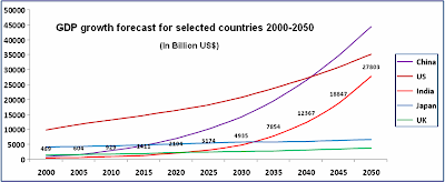
Rising oil price, currency fluctuations, supply exceeding continues global demand lead to high energy cost. As per Control Design, chemical engineers in US top the salary ladder at $63,616, followed by other engineering and technical disciplines i.e average salary of a controls engineer is up more than 8%, second largest jump what controls engineers are paid at the beginning of the new millennium. As comparison, salaries for accounting and business administration undergrads remained stable from last year at $47,429 and $44,195 respectively.

Indians working with MNCs is getting the highest salary hike of about 14 per cent on an average across the world in 2008. According to ECA International General Manager Lee Quane, “Salary increase in India is expected to be the biggest this year as companies have to keep in mind the inflation for their employees to maintain a good economic stature,” Strong growth in India is top in year 2008, this followed by by Argentina (12.7 per cent), Indonesia (11.3 per cent), Russia (11 per cent) and China remain static at 8.0%.

Let see a forum conducted recently related to situation in India.


Is this salaries soaring scenario will continue to grow ?

Reference :
Related Post

Sunday, July 13, 2008

Another NEW & FREE magazine - Pipeline & Gas Journal

Display problem ? Click HERE


Recommended :
Subscribe FREE - Pipeline Oil & Gas Journal

Chemical & Process Technology with main partner Netline has just received the greenlight from Pipeline & Gas Journal to offer another NEW & FREE magazine for loyal readers of Chemical & Process Technology.


FIRST COME FIRST SERVE ! QUICK !
There is limited offer for qualified professional and offers are on first come first serve basis. Like other hot magazine i.e Chemical Engineering, the offer reach its limit within a week.


What is Pipeline & Gas Journal ?
Pipeline & Gas Journal is the recognized authority worldwide on industry standards and Best Practices in oil and gas pipeline design, construction, operations, maintenance and integrity.

Who will benefits ?
Pipeline managers, engineers and operations personnel will benefit from this solid, reputable source of industry information, technical reviews and equipment updates. Coverage is as in-depth as it is comprehensive, with independently researched and detailed R&D discussions by industry experts, Q&A discussions with industry leaders, comparative analysis on new and emerging technologies, as well as in-depth reviews of up and coming equipment and technical advancements.

Geographic Eligibility
International

Publisher
Oildom Publishing

Side note :
Again, new released offer for Chemical Engineering (as advised earlier in "FREE Chemical Engineering is back..." has gained overwhelming requests from readers. Last week it has reached the offer limit and temporarily unavailable. Will notify once the offer is back.

Meanwhile the following still available...
Click here for others FREE magazine...

Related Post

Running Multiple Thermodynamic Model Simultaneously in HYSYS

Display problem ? Click HERE

Recommended :
Subscribe FREE - Pipeline Oil & Gas Journal

Vapor stream from column top is normal condensed via a partial or total condenser before it feed into a reflux drum. When the simulation is done in HYSYS environment with standard column template (with condenser), HYSYS only calculate the heat removal in term of energy. However, as the condenser is water cooled, how shall we estimate the water flowrate ?

Above was a question raised by a young engineer, it is a basic fundamental question. It could be simple to many of you who familiar with stream transfer and working with sub-flowsheet environment.

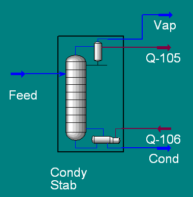
Let take an example. A condensate stabilizer with overhead condenser and condensate reboiler simulated in HYSYS as shown in following image.


Overhead vapor will be cooled by cooling water feeding from plant cooling water system while the reboiler is heated by plant hot oil system. The main simulation is using standard Equation of State (EOS) of Peng-Robinson (PR). To accurately estimate quantity of cooling water, the expected thermodynamic model is ASME steam.

If you have not known, only one Thermodynamic model (either PR or ASME Steam) can be used in single flowsheet. However, present demand is to use two thermodynamic models simultaneously.The way to handle above situation is to create a new flowsheet working in ASME Steam model while maintaining PR model in main flowsheet.

Include new sub-flowsheet
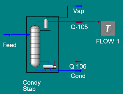
Include a Standard Sub-Flowsheet using Add Operation in Flowsheet pull down menu. Attach the energy stream Q-100 in to the sub-flowsheet FLOW-1 as shown in following image.


Define ASME Steam thermodynamic model
Enter Basis Environment sheet to define ASME Steam thermodynamic model as Basis-2. The default Basis-1 should have been assigned to PR EOS. Ensure Fluid-package-to-use for FLOW-1 sub-flowsheet is assigned to Basis-2.

Simulate Cooling Water Loop in Sub-Flowsheet FLOW-1

Enter into Sub-Flowsheet FLOW-1. The water cooler can be simulated as shown in following image.


Conclusion remark
Using Stream Transfer and Sub-Flowsheet capability, you can simulate all process and utilities systems simultaneously. This is a way to minimize transfer error, instant value update, understand how process system impacting utilities system, etc. However, it will generate a very large simulation file which will potentially required a very sophisticated computer hardware to speed-up the processing works.


Related Topic

Saturday, July 12, 2008

Back Pressure Affect Conventional PSV Set Pressure : Case Study #1 - Bonnect Vent to ATM

Display problem ? Click HERE


Recommended :
Subscribe FREE - Processing Magazine

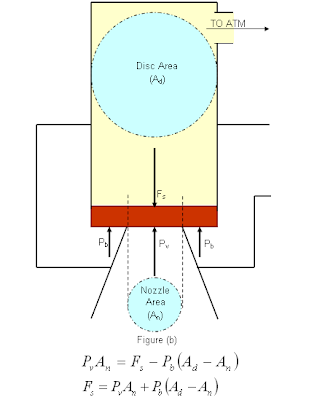
A Pressure Relief Valve (PSV) is conventional type with bonnet vent to atmosphere. This PSV is protection a pressure vessel with pre-specified design pressure of 7 barg. Maximum expected operating pressure (MOP) of the system is about 6.2 barg. The vessel has a maximum allowable working pressure (MAWP) of 8 barg. The normal continuous superimposed back pressure (PBs) is zero barg (atmosphere). PSV set pressure (Pset) has been adjusted to be inline with design pressure (DP) of 7 barg. The PSV spring has been pre-set to open when the pressure is reach 7 barg. Disc area (Ad) and nozzle area (An) are 113mm2 and 71mm2 respectively (for illustration purpose only).

Now, plant debottlenecking has introduced a new Pressure control valve (PCV) continuous releasing vapor into the common flare header as the PSV. This has resulted a constant superimposed back pressure of 0.3 barg. As per early post "How Back Pressure Affect Conventional PSV Set Pressure Subject to It Vent", increases in superimposed back pressure will results the conventional PSV open prematurely (open at lower pressure), is the system still healthy ?

From above system description;
  • PSV type : Conventional type PSV with bonnet vent to atmosphere.
  • DP = 7 barg
  • Pset (=Pv) = 7 barg
  • MOP = 6.2 barg
  • MAWP = 8 barg
  • PBs,norm = zero barg (atmosphere)
  • Ad = 113 mm2
  • An = 71 mm2
MOP / Pset = MOP / Pv = 6.2 / 7 = 88.5% < 90%. This is OK for conventional type PSV.


The spring has been pre-set to open at DP = 7 barg and expected to reach complete opening at/below 7.7 barg.

After debottlenecking...
With superimposed back pressure, Pbs=0,
==> Fs = PvAn

After debottlenecking and new PCV results increased superimposed back pressure to P'b=Pbs=0.3 barg,
(P'v is new pressure causing PSV starts to open)

==> P'vAn = Fs - P'b(Ad-An)
==> P'vAn = PvAn - P'b(Ad-An)
==> P'v = Pv - P'b (Ad-An)/An
==> P'v = 7 - 0.3 (Ad-An)/An
==> P'v = 7 - 0.3 (113 -71)/71
==> P'v = 6.82 barg

Thus, PSV will open prematurely at P'v = 6.82 barg.

MOP / P'v = 6.2 / 6.82 = 90.2% marginally > 90%. This is still OK for conventional type PSV. In case the MOP / P'v is exceeded 90%, first shall check with PSV vendor if the PSV still acceptable. If the MOP / P'v is exceeded the acceptable range, a pilot operated PSV may be employed. It can accept normal MOP/Pset upto 95% (and 98% can be achieve for some manufacturer).

Built-up back pressure (Pbb) shall be calculated (say 0.4 barg),
Pbb / P'v = 0.4 / 6.82 = 5.8% < 10%. This is still OK for conventional type PSV.

After PSV set pressure is reset...
On the other hand, if operator would like to reset the PSV setting (F's) in order the PSV to open at 7 barg with superimposed back pressure of 0.3 barg, another assessment where the PCV is offline shall be checked. When PCV is offline, Pb = 0 barg.

After reseting, P'v = 7 barg, P'b = 0.3 barg,

==> P'vAn = F's - P'b(Ad-An)
==> F's = P'vAn + P'b(Ad-An)

When PCV is offline, superimposed back pressure will drop to P"b=0 barg,
with new opening pressure of P"v,

==> P"vAn = F's - P"b(Ad-An)
==> P"vAn = P'vAn + P'b(Ad-An) - P"b(Ad-An)
==> P"v = P'v + (P'b - P"b)(Ad-An)/An
==> P"v = 7 + (0.3-0)(113-71)/(71)
==> P"v = 7.18 barg

The new opening pressure will potentially 7.18 barg which is still below the Maximum Allowable Working pressure (MAWP) of 8 barg. Thus, this is still acceptable. In case the MAWP is lower than 7.18 barg, the new PSV setting shall be reduced accrodingly.

Observations
In this case study, there are some observation can be deduced :
  • A conventional type PSV with bonnet vented to atmosphere, increases in superimposed back pressure will results conventional PSV open prematurely (open at lower pressure)
  • Premature opening pressure shall be checked to maintain a healthy margin of 10% between Maximum operating pressure (MOP) and premature opening pressure
  • New built-up back pressure shall be checked to ensure it still lower than 10% of premature opening pressure
  • In case above healthy criteria can not be met, may consider reset the PSV spring setting in order to increase the set pressure of PSV
  • With increase set pressure, the maximum opening pressure PSV shall be maintained below the Maximum allowable Working Pressure (MAWP) of protected system.

Related Post