Display problem ? Click HERE
 Few years back involved in a commissioning of a gas processing plant. The process engineer hasover-estimated the pressure drop on the Deminineralized Water (DW) pump discharge line (actual pressure drop on site is much lower). Extra pressure drop will be throttled by the manual and/or automatic control valve. This implied that the DW pump works "extra" as well as the valve.
There are a few impacts associate with this simple over-estimate :
- Increased pump power consumption
- Extra pressure drop across control valve increases wear and tear and reduce valve lifespan.
- Operates at higher pressure level increases safety risk
As the projects is promoting Green philosophy and ALARP principles, the management has decided to minimize the consequence and/or optimize above situation. There are few straight forward to above situation :
- Change fixed speed to variable speed
- Trim impeller
Change speed of motor is considered one the very good option as the system will reduce pump head to suit system curve demand, reduce power consumption and operates at lower pressure (reduce safety risk). In additional, in the event the pressure drop on the system increases in future due to fouling, corroded pipe, etc, the pump speed can be increases anytime to meet the new demand. Nevertheless, this involved inclusion of extra device like frequency inverter and cabling, potential motor size change, extra installation & testing time and delay in start-up, this option has been "parked" for future consideration.
Trim pump impeller is another way to tackle above issue. Although it is not the best option, it is considered a reasonable and acceptable option during this commissioning and start-up period. Now, the question is
how much should i trim the impeller in order to meet new condition ?
The Affinity Law is concept that you should looks for. The Affinity Law is one of common concept in pump industry and used widely in estimating pump new performance in the event of impeller size changed, motor speed changed and both of above. Umbrella
The Affinity Law states that for similar conditions of flow (i.e. substantially same efficiency) the capacity (Q) will vary directly with the ratio of speed (N2/N1) and/or impeller diameter (D2/D1) and the head with the square of this ratio at the point of best efficiency (BEP). Other points to the left or right of the best efficiency point will correspond similarly. Refer table to view the relation between capacity (Q), speed (N), impeller size (D), pump head (H) and motor power (bhp).
 Figure 1 : Affinity Law Relationship
Source : Centrifugal Pump : Design & Application
(Click to view larger chart)
Above law is a fundamental relationship which derived from theory. There is some deviation of performance in real world. The higher the percentage of impeller being trimmed, the the higher the deviation is. Thus, a correction factor (Kc) shall be included in order to correct the performance. Following Impeller Trim Correction may be used to correct the the performance.
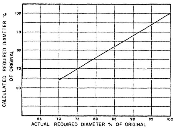 Figure 2 : Impeller Trim Correction
Source : Centrifugal Pump : Design & Application
(Click to view larger chart)
The are two conditions associate to trimming of impeller.
- Specific speed, Ns less than 2500, Impeller trim to be limited to 70%. Trim cut below 70% may cause significant efficiency drop and instable operation.
- Specific speed, NS = 2500-4000, Impeller trim to be limited to 90%. Trim cut
below 90% may cause possible hydraulic problems associated with inadequate vane overlap.
Example,
An existing pump impeller size is 7-in with pump head of 135 ft. What is the impeller trim is required to reduce pump head to 90 ft ?
H2/H1 = (D2/D1)^2
(D2/D1) = (H2/H1)^0.5
(D2/D1) = (90/135)^0.5
(D2/D1) = 0.8163 (81.63%)
From figure 2 : Impeller Trim Correction chart,
Corrected (D2/D1) = 84% (more than 70%, OK for Ns less than 2500)
Thus, D2 = 0.84 x 7 = 5.88 inches.
The associate new Flow (Q) and Power (bhp) can be calculated according to above equation with the D2/D1. The new efficiency can be recalculated base on the Specific Speed (Ns) as discussed in "Estimate Pump Efficiency base on Specific Speed (Ns)".
Above demonstrates the new sets Flow, Power, Head and efficiency for a Trimmed impeller for a single point. If you have the existing pump curve (H vs Q), you may re-establish the new curve (H2 vs Q2) base on existing curve (H1 vs Q1) for a trimmed impeller size (D2). With new curve, you may read the H2 at required pump flow i.e. Qr. If the H2 @ Qr is lower than required pump head (Hr), it signified the impeller is over-trimmed and D2 shall be increased (reduced trim percentage), vice versa until you get the curve with same pump flow (Q1=Q2=Qr) with reduced pump head (H2=Hr).
Related Topic
Related Topic
No comments:
Post a Comment